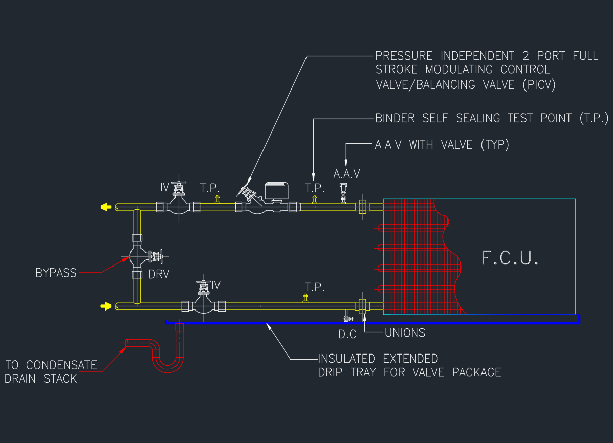
A Fan Coil Unit (FCU) is a key component of HVAC systems, used to control room temperature by circulating air through a chilled or hot water coil.
Proper FCU connection detailing ensures efficient operation, easy maintenance, and balanced water flow within the chilled water system.
This post provides a free AutoCAD DWG file showing the Typical Detail of FCU Connections, ideal for MEP and HVAC engineers.
What Is an FCU Connection?
An FCU connection links the fan coil unit to the chilled water supply and return lines.
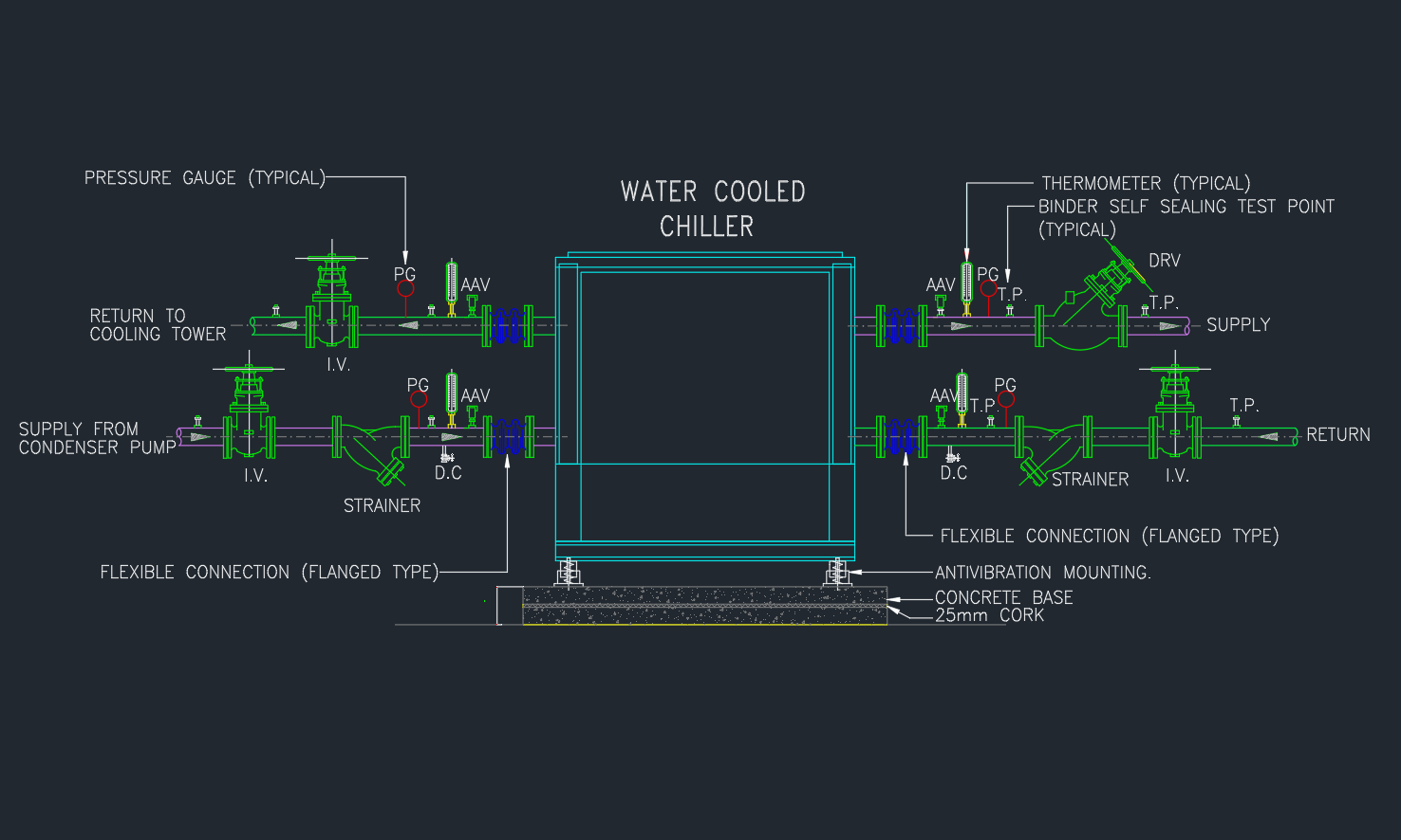
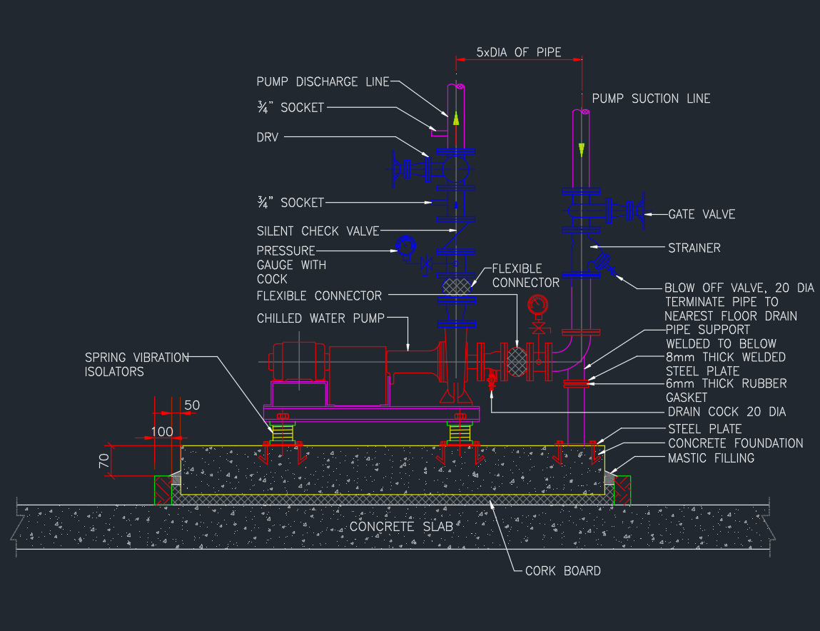
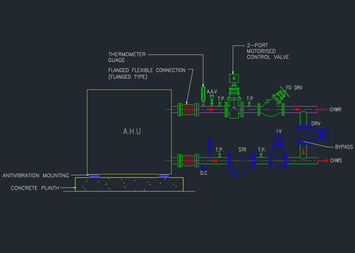
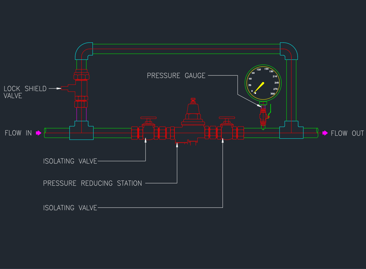
The connection typically includes valves, strainers, flexible connectors, and control devices to manage flow, pressure, and maintenance access.
FCUs are often installed in ceiling spaces, mechanical rooms, or under raised floors for local cooling and heating control.
Main Components of FCU Connections
| No. | Component | Function |
|---|---|---|
| 1 | Isolation Valves (Ball / Butterfly) | For maintenance and shut-off |
| 2 | Y-Strainer | Protects coil and valve from debris |
| 3 | Control Valve (2-Way / 3-Way) | Regulates chilled water flow |
| 4 | Flexible Connector (Hose) | Absorbs vibration and noise |
| 5 | Union / Flanged Joint | Allows coil removal for service |
| 6 | Drain Valve | Enables system flushing |
| 7 | Air Vent Valve | Removes trapped air from coil |
| 8 | Temperature & Pressure Test Points | For commissioning and balancing |
AutoCAD DWG Download
This DWG file includes:
- FCU connection schematic and layout detail
- Typical chilled water supply and return lines
- Control valve and strainer arrangement
- Flexible hose and insulation note
- Plan and section views for mechanical design
Installation Guidelines
- Maintain proper flow direction: bottom in, top out for coil.
- Install strainers before control valves.
- Provide drain and air vent at low/high points respectively.
- Use flexible connectors on both supply and return sides.
- Include union joints near coil for easy removal.
- Apply closed-cell insulation to prevent condensation.
Applicable Standards
- ASHRAE 90.1 / 62.1 – HVAC Design & Energy Standards
- SMACNA – Mechanical Equipment Installation
- ASME B31.9 – Building Services Piping
- BS EN 12599 – HVAC Testing and Balancing
Advantages of Proper FCU Piping Connection
✅ Smooth operation and efficient cooling performance
✅ Reduced vibration and water hammer
✅ Easy maintenance and balancing
✅ Extended equipment life
✅ Leak-free system design
Conclusion
The Typical Detail of FCU Connections is crucial for efficient chilled water system performance.
Download the AutoCAD DWG drawing and use it as a reference for your HVAC design, coordination, or construction documentation.