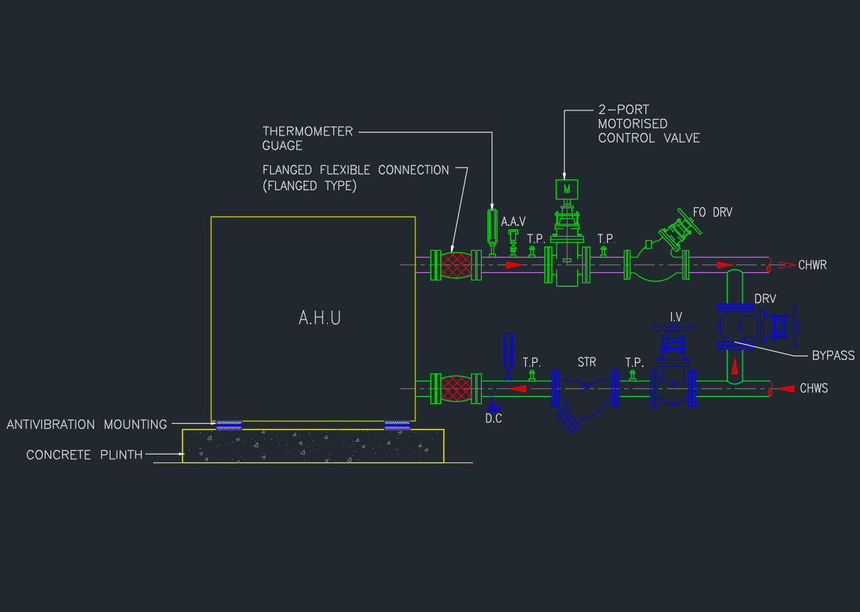
The Air Handling Unit (AHU) is a major part of any HVAC chilled water system. It cools or heats air that is supplied to the building through ducts.
To ensure stable operation and maintain coil performance, the chilled water supply and return piping must be properly connected with valves, strainers, and flexible joints.
This post provides a Typical Detail of AHU Chilled Water Piping Connections in AutoCAD DWG format, ready for engineers, MEP designers, and drafting professionals.
What Is AHU Chilled Water Piping?
An AHU chilled water piping system circulates chilled water from the chiller plant through the AHU coil, where it absorbs heat from the air.
A correct connection detail ensures smooth water flow, ease of maintenance, and effective temperature control.
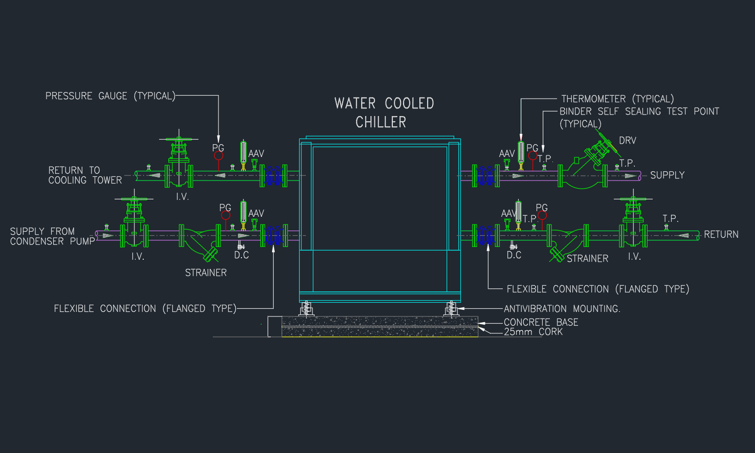
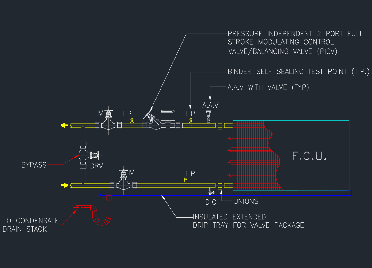
The connection typically includes:
- Supply and return lines (insulated)
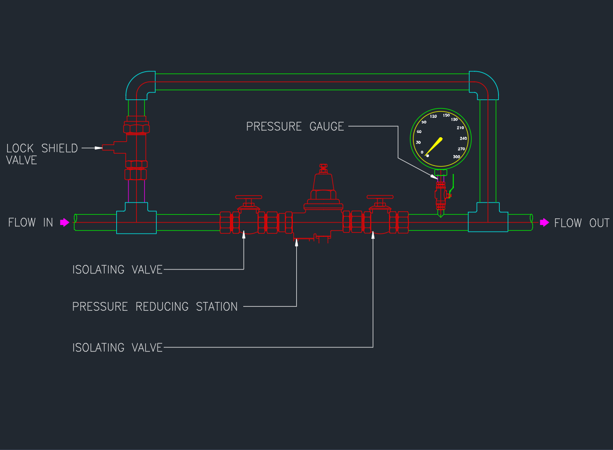
- Isolation and control valves
- Strainer, unions, and gauges
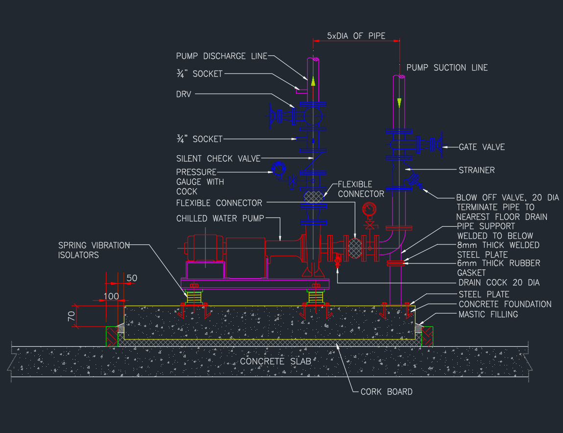
- Flexible connectors for vibration absorption
Typical Components of AHU Piping Connections
| No. | Component | Function |
|---|---|---|
| 1 | Butterfly Valve / Ball Valve | Isolates flow for service or balancing |
| 2 | Y-Strainer | Removes dirt and debris before entering the coil |
| 3 | Control Valve (2-Way or 3-Way) | Regulates water flow according to temperature demand |
| 4 | Flexible Connector | Absorbs vibration and prevents coil stress |
| 5 | Union / Flanged Joint | Allows easy removal of coil and valve assembly |
| 6 | Drain Valve | For system flushing or coil maintenance |
| 7 | Air Vent | Removes trapped air in the piping system |
| 8 | Temperature and Pressure Gauge | For performance monitoring and balancing |
Installation Guidelines
- Maintain correct water flow direction (usually bottom in, top out).
- Install flexible connectors on both supply and return sides.
- Place strainer before control valve to protect it from clogging.
- Provide unions/flanges for coil and valve assembly removal.
- Include drain and vent valves at low and high points.
- Use insulation to prevent condensation.
Applicable Standards
- ASHRAE 90.1 / 62.1 – Energy & Ventilation Efficiency
- SMACNA HVAC Standards – Piping Construction
- ASME B31.9 – Building Services Piping
- BS EN 12599 – Testing and Balancing Procedures
Benefits of Proper AHU Piping Connection
✅ Increases system efficiency
✅ Reduces vibration and water hammer
✅ Simplifies coil maintenance
✅ Ensures accurate temperature control
✅ Extends equipment lifespan
Conclusion
A well-designed AHU chilled water piping connection is critical to achieving reliable HVAC performance.
Download the AutoCAD DWG file to use this detail in your mechanical design, shop drawings, or MEP documentation.