Introduction
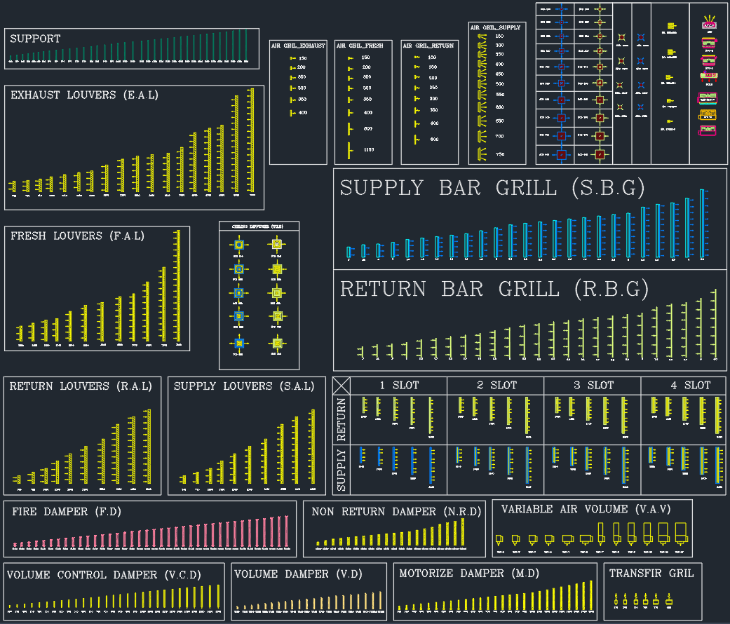
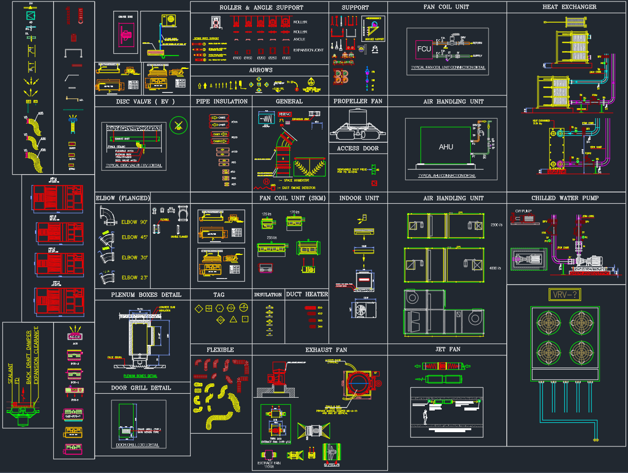
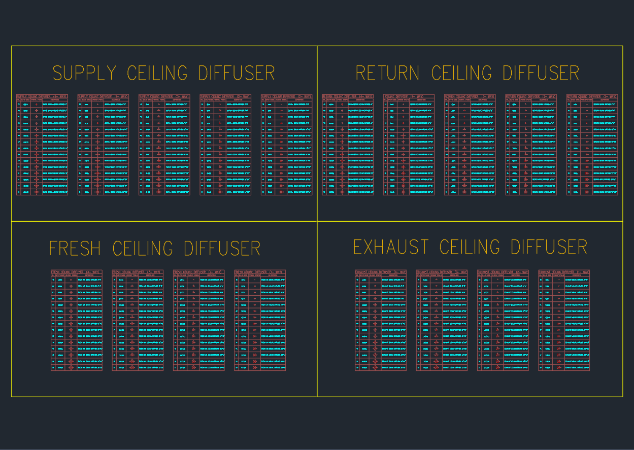
A Square Diffuser is a key air terminal device used in HVAC systems for distributing conditioned air uniformly throughout interior spaces. This AutoCAD DWG drawing includes a complete collection of supply, return, fresh air, and exhaust ceiling diffuser symbols — ideal for MEP, HVAC, and building services engineers designing air distribution systems in AutoCAD.
Drawing Overview
This DWG file provides four diffuser categories, each precisely detailed and ready for integration into mechanical drawings:
1. Supply Ceiling Diffuser
-
Used for supply air outlets in air conditioning systems.
-
Distributes air evenly across the occupied zone.
-
Available in multiple standard sizes (150×150 mm to 600×600 mm).
-
Layered with directional flow patterns for easy identification in AutoCAD.
-
Suitable for ceiling-mounted installations with plenum box connections.
2. Return Ceiling Diffuser
-
Designed for return air intakes, maintaining balanced airflow in closed-loop systems.
-
Includes frame and grille details to match architectural ceiling finishes.
-
Used in conjunction with volume control dampers (VCD) or non-return dampers (NRD).
-
Commonly placed near supply diffusers to optimize air circulation.
3. Fresh Ceiling Diffuser
-
Dedicated for fresh air intake systems, supplying outdoor air to maintain indoor air quality (IAQ).
-
Includes typical configurations with filter or damper integration.
-
Essential for ventilation systems in commercial, office, or public buildings.
4. Exhaust Ceiling Diffuser
-
Used for exhausting air from kitchens, restrooms, or mechanical rooms.
-
Designed to handle negative pressure conditions.
-
Compatible with duct-mounted exhaust fans or centralized return systems.
-
Includes standard frame sizes and core designs for visual coordination.
Technical Specifications
| Parameter | Description |
|---|---|
| File Format | AutoCAD DWG |
| View Type | 2D Top View |
| Scale | 1:1, ready for layout |
| Standard Sizes | 150 mm, 300 mm, 450 mm, 600 mm |
| Layer System | Organized by airflow type (Supply / Return / Exhaust / Fresh) |
| Compatibility | AutoCAD 2007 and above |
| Standards | Based on ASHRAE and SMACNA HVAC design conventions |
| Usage | HVAC tender, coordination, and as-built drawings |
Applications
This DWG library is perfect for:
-
HVAC Air Distribution Layouts – Ceiling diffuser placement in mechanical plans.
-
MEP Coordination Drawings – Integration with ducts, lighting, and ceiling grids.
-
Ventilation System Design – Fresh and exhaust air balancing.
-
Architectural Integration – Aligning ceiling grilles with aesthetic layouts.
-
Construction and Shop Drawings – Fabrication and installation documentation.
Design Features
-
Multi-Zone Airflow Patterns
Each diffuser includes directional vanes representing 1-way, 2-way, 3-way, and 4-way air patterns. -
Balanced Air Performance
The DWG layout is drawn according to standard diffuser discharge angles for uniform air throw. -
Easy Tagging
Each diffuser block includes space for airflow labels (CFM or L/s), simplifying mechanical documentation. -
Ceiling Mount Compatibility
Designed to integrate seamlessly with T-bar suspended ceilings and modular ceiling tiles. -
Layered Color Scheme
Organized by diffuser function (Supply – Blue, Return – Green, Fresh – Yellow, Exhaust – Red) for visual clarity in complex HVAC layouts.
Installation Notes
-
Height: Typically installed at ceiling level, 2.4 to 3.0 meters from the floor.
-
Spacing: Maintain equal spacing between supply and return diffusers for balanced air circulation.
-
Air Volume: Select diffuser size according to design airflow (50–350 CFM typical).
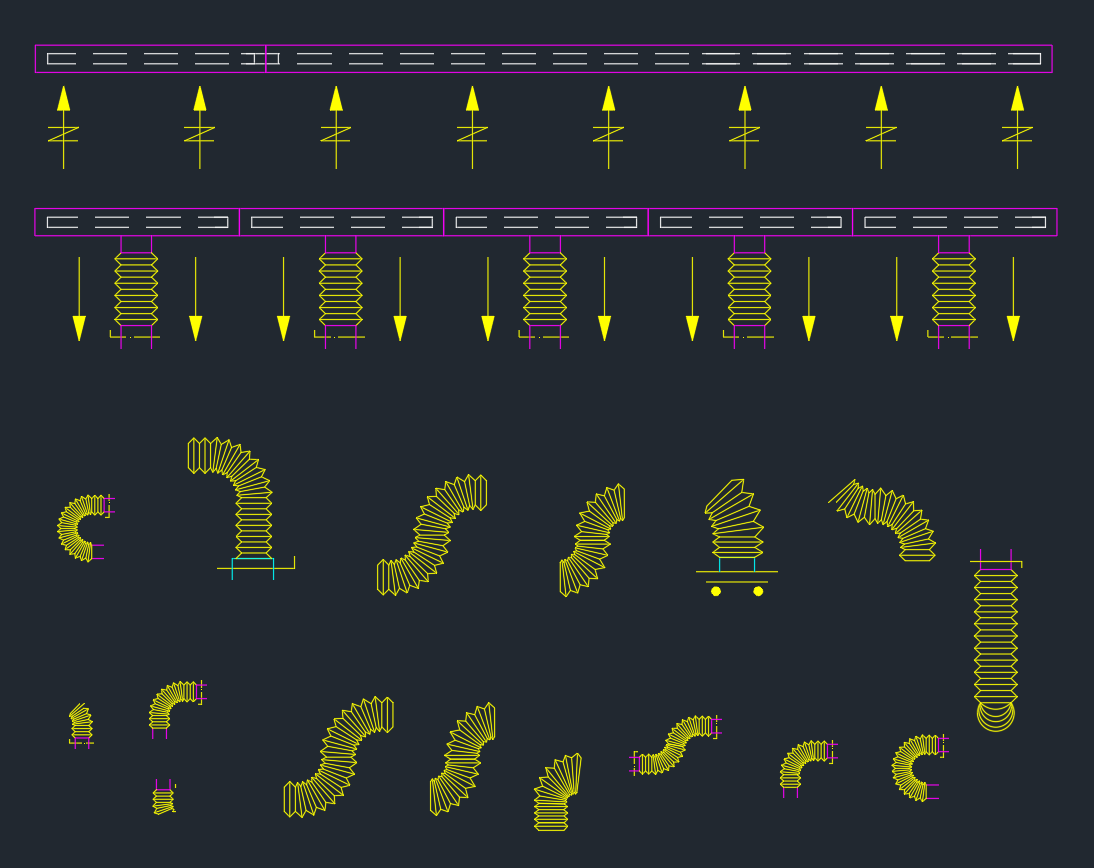
-
Connection: Use flexible ducts or plenum boxes for noise isolation and installation flexibility.
-
Balancing: Combine with Volume Control Dampers (VCD) to fine-tune airflow during commissioning.
Advantages
✅ Comprehensive Set – Includes all diffuser types for HVAC design.
✅ Professional Drafting Quality – Standardized line weights and scaling.
✅ Time-Saving – Ready-to-use blocks with labeled airflow directions.
✅ Customizable Layouts – Easily rescale, edit, or mirror for any project type.
✅ Layer Organized – Simplifies visibility control and printing in AutoCAD.
Conclusion
The Square Ceiling Diffuser DWG library is an essential resource for HVAC and MEP engineers designing air distribution systems. It provides all diffuser types — supply, return, exhaust, and fresh air — in a standardized and editable AutoCAD format, ensuring accuracy, visual consistency, and fast integration into your mechanical plans.
This drawing is perfect for commercial, residential, and industrial HVAC layouts, helping designers deliver efficient, professional-quality documentation.
⬇ Download AutoCAD File