Introduction
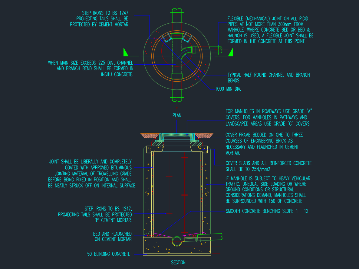
A Site Drainage System is an essential part of civil infrastructure design, responsible for managing surface and subsurface water to prevent flooding, erosion, and structural damage. This AutoCAD DWG file contains complete construction details for manholes, catchpits, and drainage pipe connections, drawn according to standard civil and municipal engineering specifications.
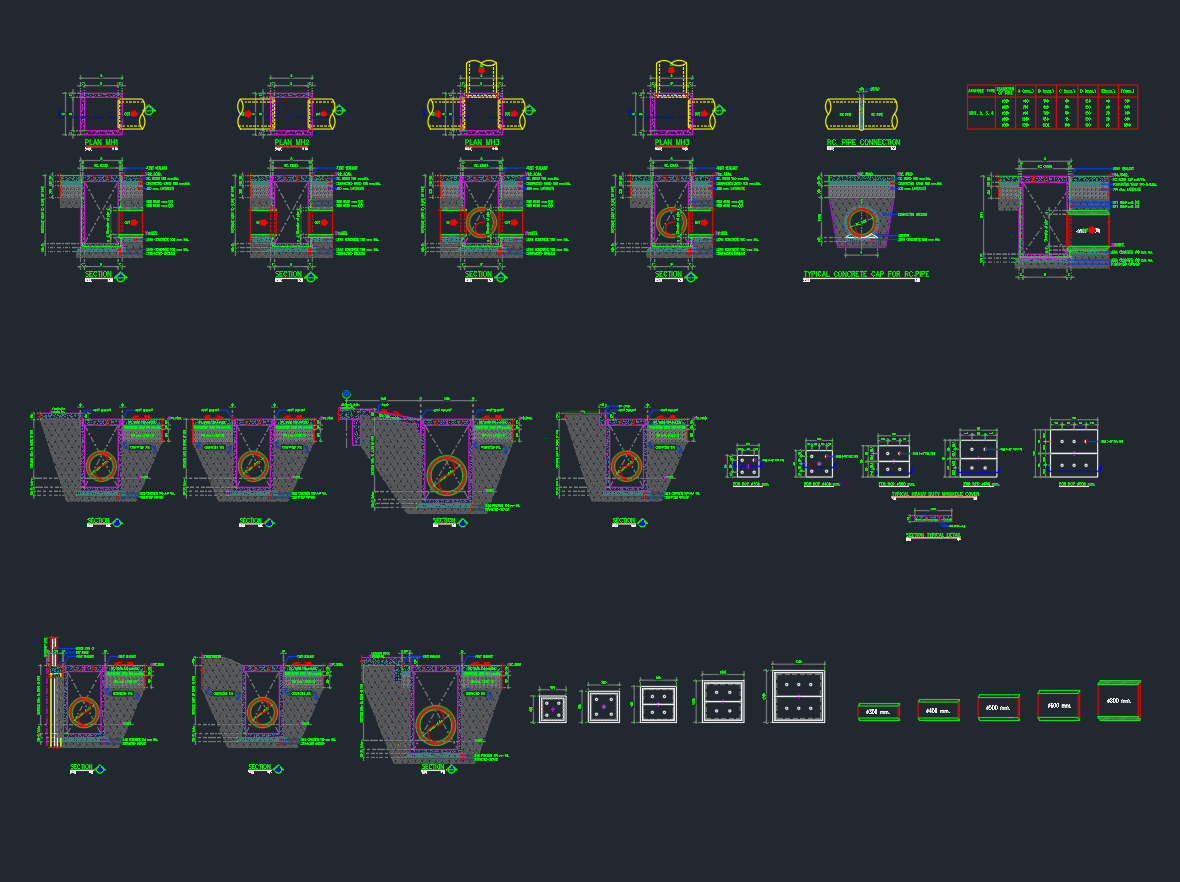
The drawing includes plan, section, and elevation views, covering all structural and hydraulic details necessary for proper drainage system installation.
Key Components in the Drawing
1. Manhole Layout Plans (MH1–MH6)
Each manhole type is designed for different pipe sizes and depths. The plans show:
-
Pipe inlet and outlet positions
-
Internal clear dimensions
-
Manhole cover frame placement
-
Flow channel (benching) profiles
These layouts ensure consistent hydraulic performance and accessibility for inspection and maintenance.
2. Catchpit and Inlet Structures
The catchpit drawings include details for sediment traps and grating installation, allowing debris to settle before water flows into the drainage network.
-
Typical Concrete Catchpit (Pre-Cast Option)
-
Reinforced Concrete (RC) In-Situ Construction
-
Access Ladder and Step Details for safe maintenance
3. Pipe Connections and Benching Details
-
Standardized pipe connections for PVC, RC, and HDPE pipes
-
Sloped benching for smooth hydraulic flow
-
Concrete haunching around pipe inlets for structural support
-
Dimensional reference for various pipe diameters (Ø150 to Ø600 mm)
4. Sectional Details
Each manhole section illustrates:
-
Reinforcement cage layout for wall and base slab
-
Concrete strength grades (typically C30/37 or as specified)
-
Waterproofing layers and bituminous coatings
-
Pipe invert levels and cover-to-top dimensions
-
Precast ring configurations for modular assembly
5. Manhole Schedule Table
A tabulated summary provides:
-
Manhole reference ID (MH1, MH2, etc.)
-
Depth from ground level to invert level
-
Internal chamber dimensions
-
Pipe size compatibility
-
Structural material type (Precast / In-Situ)
This schedule simplifies design coordination and construction sequencing.
Material and Construction Specifications
| Component | Specification |
|---|---|
| Concrete Grade | C30/37 reinforced concrete |
| Manhole Rings | Precast RC or in-situ cast with bituminous coating |
| Cover Slab | Reinforced concrete with galvanized steel lifting eyes |
| Manhole Cover | Ductile iron frame, class D400 (EN 124 standard) |
| Pipes | uPVC, RC, or HDPE depending on diameter |
| Reinforcement | High-yield deformed bars (fy = 500 MPa) |
| Joint Sealant | Non-shrink grout or waterproof epoxy compound |
| Access Steps | Galvanized mild steel or polypropylene encapsulated rungs |