Introduction
A Shell and Tube Heat Exchanger is one of the most common types of heat exchangers used in industrial plants.
It transfers heat between two fluids — one flowing inside the tubes and the other through the surrounding shell.
This equipment is found in power plants, refineries, HVAC systems, and chemical process units due to its high efficiency, robustness, and easy maintenance.
1. What Is a Shell and Tube Heat Exchanger?
A shell and tube exchanger consists of:
-
A bundle of tubes through which one fluid flows (the tube side)
-
A shell that surrounds these tubes, carrying the second fluid (the shell side)
Heat transfers through the tube walls — allowing one fluid to be heated or cooled without direct mixing.
🧩 Common uses include cooling compressed gas, condensing steam, and heating process liquids using hot oil or steam.
2. Main Components
| Component | Description |
|---|---|
| Shell | Outer vessel that holds one of the fluids (typically larger volume side). |
| Tube Bundle | Group of tubes inside the shell that carries the second fluid. |
| Tube Sheets | Plates that hold the tube ends and separate shell/tube fluids. |
| Baffles | Metal plates that direct fluid flow within the shell, enhancing turbulence and heat transfer. |
| Front & Rear Heads | Enclosures for tube-side inlet and outlet. Types: fixed, floating, or U-tube. |
| Nozzles / Connections | Inlet/outlet for both fluids, usually marked as shell inlet (S-in), shell outlet (S-out), tube inlet (T-in), tube outlet (T-out). |
| Support Saddles | Structural supports that hold the exchanger horizontally on foundations. |
3. Flow Configurations
There are three main flow arrangements in shell and tube exchangers:
| Type | Flow Direction | Description |
|---|---|---|
| Parallel Flow | Both fluids flow in the same direction | Simplifies design but less efficient. |
| Counter Flow | Fluids move in opposite directions | Most efficient for maximum heat recovery. |
| Cross Flow | Fluids flow perpendicular to each other | Common in air-cooled and compact designs. |
💡 Counter-flow arrangement is preferred when a large temperature difference or higher heat recovery is required.
4. Types of Shell and Tube Heat Exchangers (per TEMA Classification)
| Type | Front End | Shell | Rear End | Remarks |
|---|---|---|---|---|
| E | One-pass shell | Fixed tubesheet | Simplest, economical design | |
| F | Two-pass shell | Single baffle divider | Compact, higher efficiency | |
| K | Floating head | Removable tube bundle | Easy cleaning, for fouling fluids | |
| U | U-tube bundle | One tubesheet only | Allows thermal expansion |
TEMA (Tubular Exchanger Manufacturers Association) standards define symbols like E, F, K, U, W to specify head, shell, and rear configurations.
5. Working Principle
-
Hot and cold fluids enter through their respective nozzles.
-
Tube-side fluid flows inside tubes, shell-side fluid flows across them.
-
Heat transfer occurs via conduction through the tube walls and convection on both sides.
-
Baffles guide shell-side flow to improve turbulence and thermal efficiency.
-
Outlet streams exit at desired temperatures, depending on the duty and flow rate.
🌡️ The exchanger’s performance depends on flow velocity, temperature difference, fouling factors, and material conductivity.
6. Materials of Construction
| Component | Common Materials |
|---|---|
| Tubes | Stainless Steel, Cu-Ni Alloy, Titanium |
| Shell | Carbon Steel, Stainless Steel |
| Tube Sheet | Carbon Steel / SS Clad |
| Gaskets | PTFE, Graphite, Spiral Wound |
| Baffles | Carbon Steel / SS Plate |
| Bolts / Nuts | ASTM A193 B7 / A194 2H |
Material selection depends on pressure, temperature, and corrosion characteristics of the process fluids.
7. Advantages
✅ High pressure and temperature capability
✅ Easy to maintain (cleaning tube bundle)
✅ Suitable for wide range of fluids
✅ Long operational life
✅ Scalable for large heat duties
8. Applications
-
Refinery & petrochemical units (feed/effluent exchangers)
-
Power generation (condenser cooling)
-
Gas compression systems (aftercoolers)
-
Chemical & fertilizer plants
-
HVAC chillers and oil coolers
9. P&ID Symbol for Shell and Tube Heat Exchanger
In a P&ID (Piping & Instrumentation Diagram), the symbol typically includes:
-
A rectangle or oval representing the shell
-
Multiple parallel lines for tubes
-
Inlet and outlet arrows on opposite sides
-
Tag number like E-101 or HEX-201
Example:
Tag example: E-301 – Heat Exchanger in system 300 (Shell & Tube Type)
10. Typical Design Data (Example)
| Parameter | Typical Range |
|---|---|
| Design Pressure | 10–50 barg |
| Design Temperature | up to 300 °C |
| Heat Duty | 50 kW to >10 MW |
| Tube Diameter | 12–25 mm |
| Tube Pitch | 1.25 × OD |
| Tube Length | 2–6 m |
| Flow Arrangement | Counter-flow (preferred) |
11. AutoCAD / DWG Download
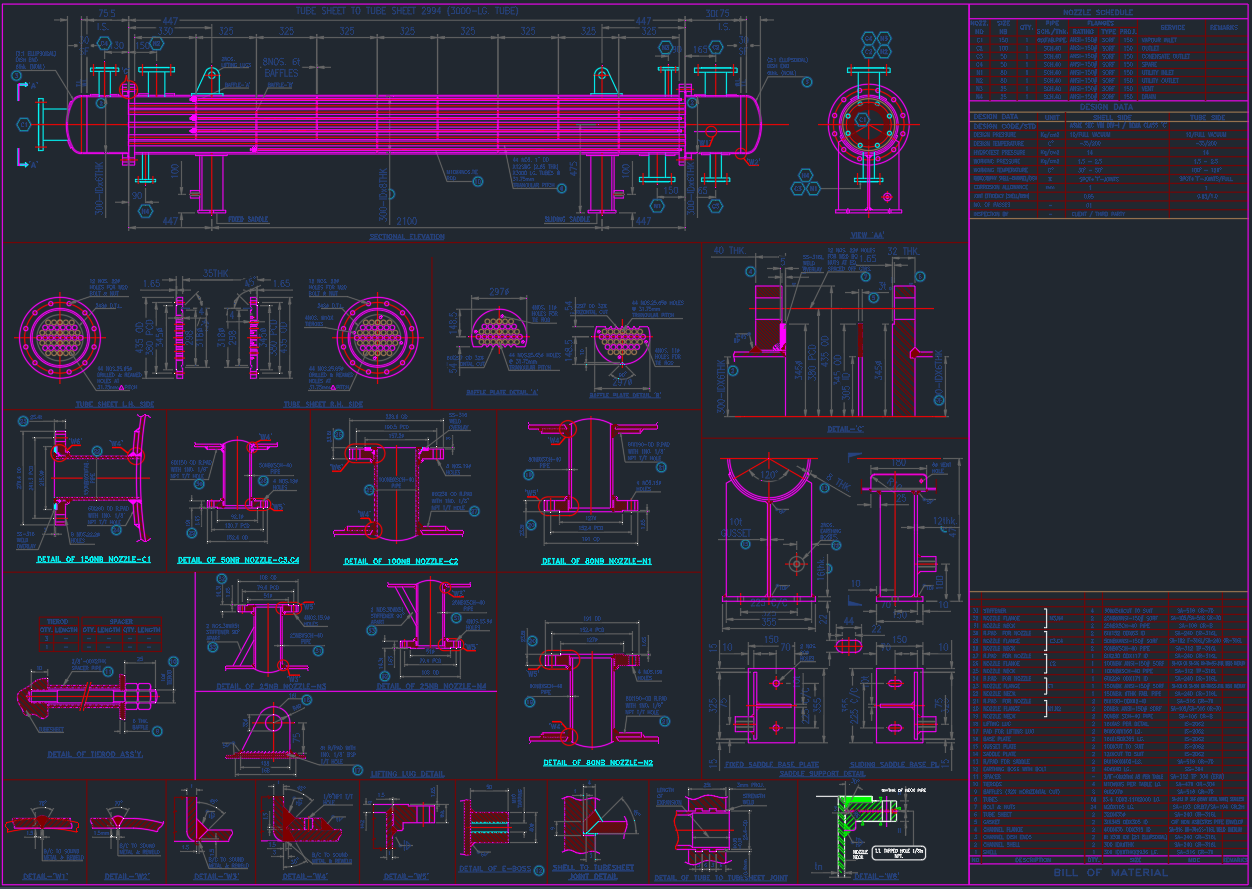
Get a ready-to-use Shell and Tube Heat Exchanger CAD Block (DWG) in plan and elevation views, including:
-
Shell, tube bundle, nozzles, and supports
-
P&ID symbol
-
Tag annotation layer
-
Compatible with AutoCAD 2007+
Conclusion
A Shell and Tube Heat Exchanger is the backbone of industrial heat transfer systems.
Its flexibility, proven design, and thermal efficiency make it the preferred choice across refineries, power plants, and chemical industries.