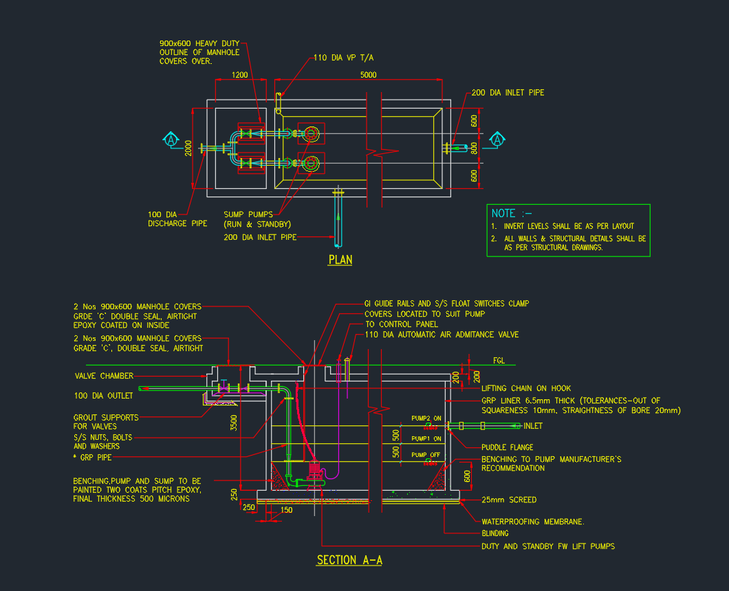
A Pumping Chamber is a vital structure used in plumbing, drainage, and water supply systems to collect and pump wastewater, stormwater, or treated water from low-level areas to the main drainage line.
This drawing provides a detailed AutoCAD DWG showing Pumping Chamber Details, including plan, section, pipe connections, valves, and pump arrangement.
It is ideal for civil, plumbing, and MEP engineers designing water supply or drainage infrastructure.
What Is a Pumping Chamber?
A pumping chamber (also known as a sump or wet well) houses one or more pumps that lift water to a higher elevation.
It is commonly used when gravity flow is not possible, such as in basements, underground car parks, and sewage networks.
Typical applications include:
- Stormwater and sewage lifting stations
- Building basement sump systems
- Water treatment plants
- Irrigation and pressure boosting systems
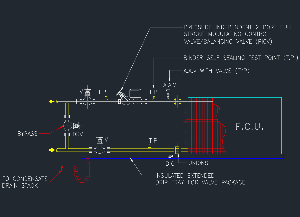
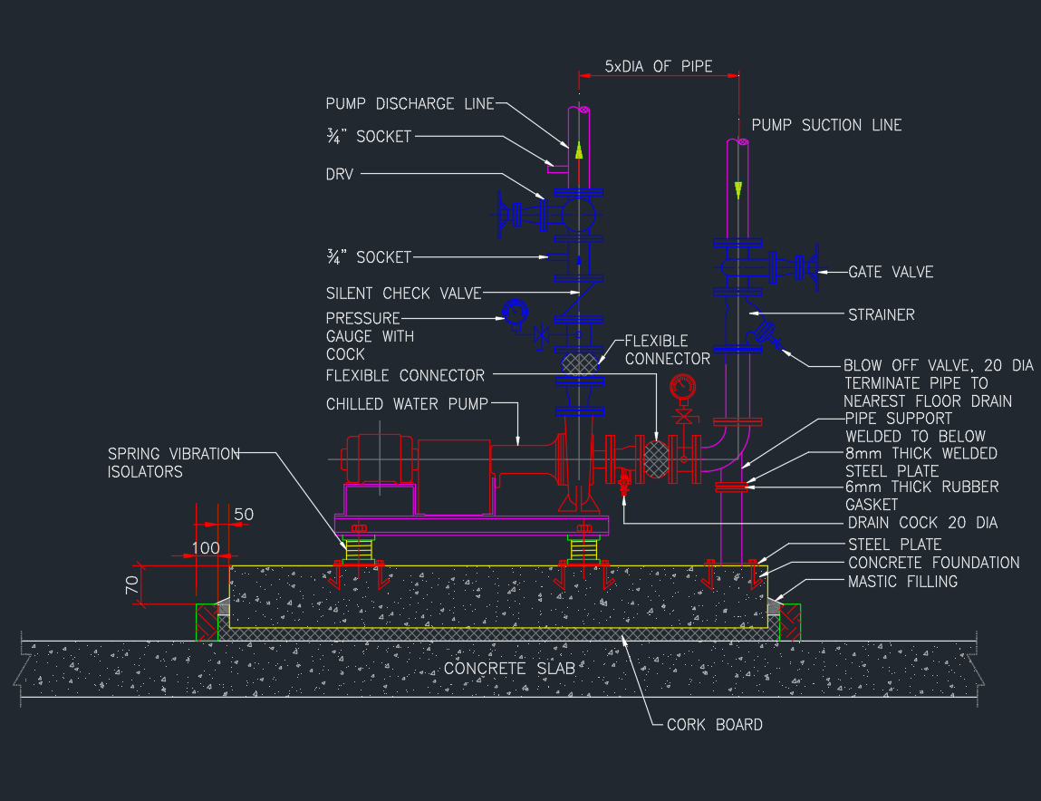
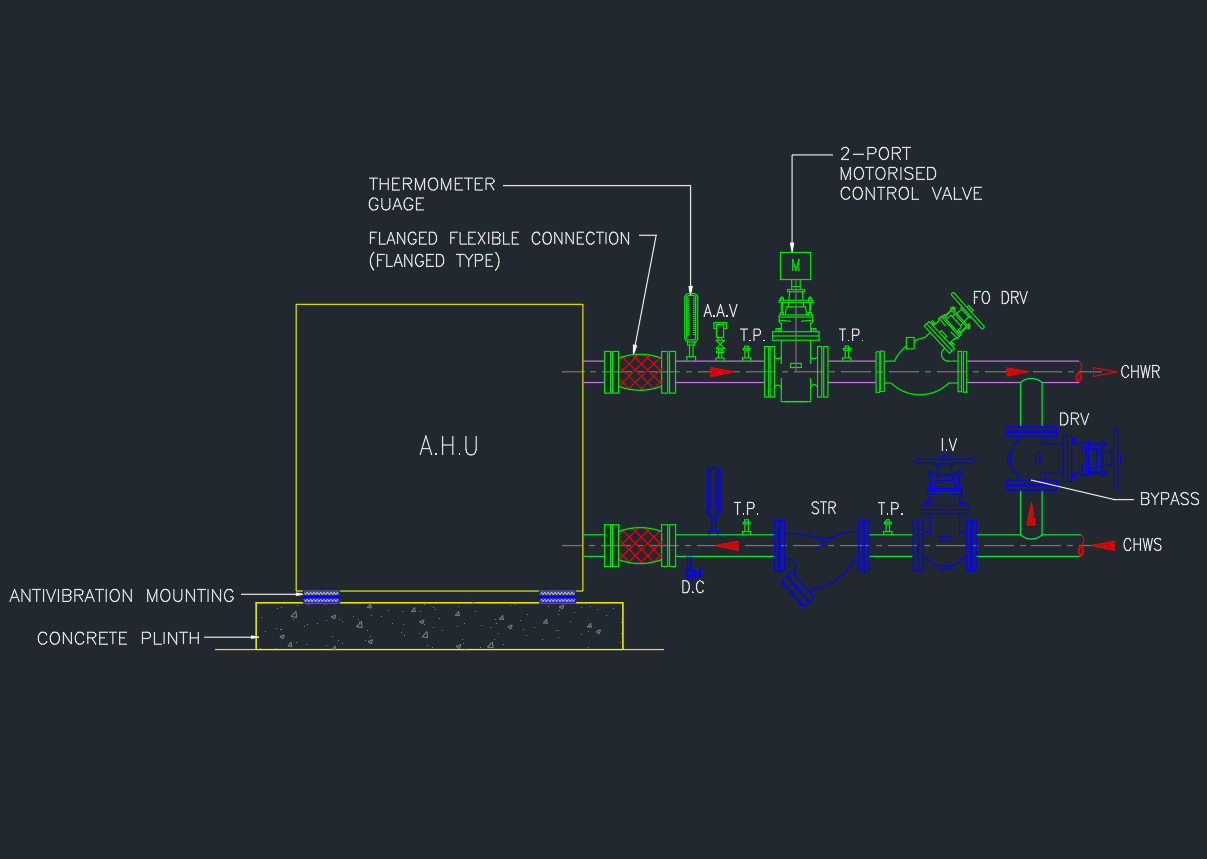
Key Components in Pumping Chamber Details
| No. | Component | Description |
|---|---|---|
| 1 | Concrete Chamber | Reinforced structure designed to resist water pressure and soil load |
| 2 | Submersible Pumps | Transfer wastewater or stormwater to higher level |
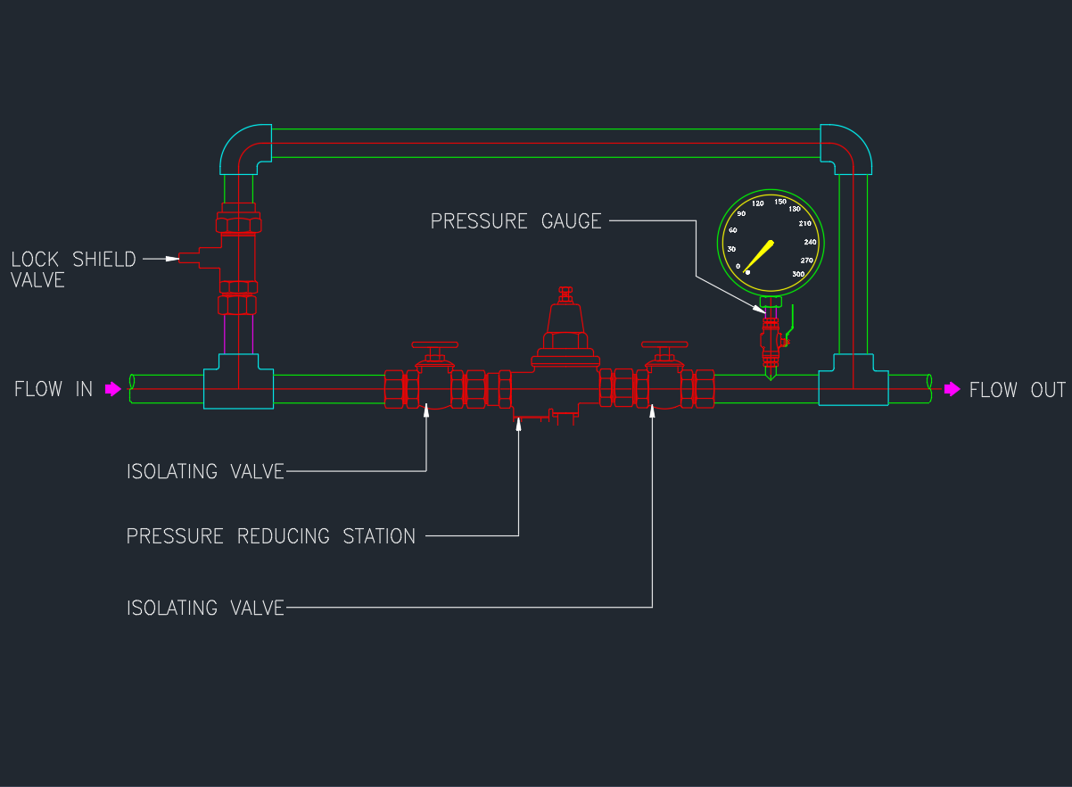
| 3 | Non-Return Valve (NRV) | Prevents backflow when pump stops |
| 4 | Gate / Isolation Valve | Allows maintenance or isolation of discharge line |
| 5 | Float Switch or Level Sensor | Automatically starts/stops pumps based on liquid level |
| 6 | Access Cover & Ladder | Provides maintenance entry for operators |
| 7 | Vent Pipe | Releases trapped gases and odors |
| 8 | Discharge Pipe & Manifold | Carries pumped water to main drainage line |
AutoCAD DWG Download
The DWG file includes:
- Plan and sectional views of pumping chamber
- Pump layout, pipe connections, and NRV details
- Electrical and control wiring notes (optional)
- Dimensioned and layered drawing for easy modification
Installation Guidelines
- Ensure chamber base is level and watertight.
- Provide adequate ventilation and access cover.
- Use dual pumps for standby operation where required.
- Install NRV and gate valve on each discharge line.
- Include electrical isolation switch near the chamber.
- Test pumping operation before commissioning.
Applicable Standards
- BS EN 12056-4 – Gravity Drainage Systems inside Buildings
- BS EN 752 – Drain and Sewer Systems outside Buildings
- ASHRAE & CIBSE – Mechanical Building Services Standards
Advantages
✅ Safe and reliable wastewater lifting
✅ Compact chamber design for limited spaces
✅ Easy pump maintenance and inspection
✅ Prevents flooding in basements or low-lying areas
✅ Compatible with various pump types
Conclusion
The Pumping Chamber Details AutoCAD drawing is an essential reference for plumbing, civil, and MEP engineers working on building or infrastructure drainage systems.
Download the DWG file to use as a standard layout for water and wastewater pumping station design.