A Pressure Reducing Valve (PRV) Station is a key part of any building water supply or fire protection system where high inlet pressure must be reduced to a safe and stable outlet pressure.
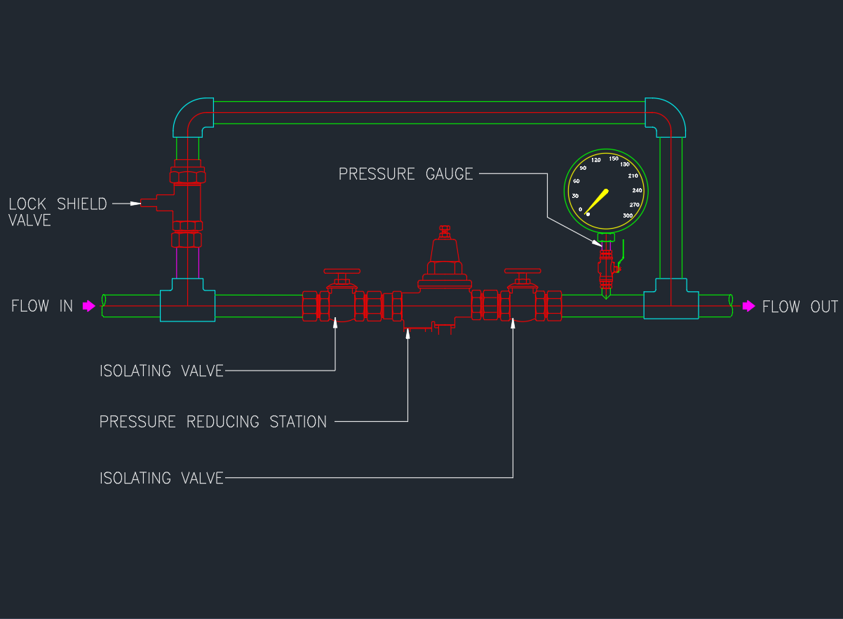
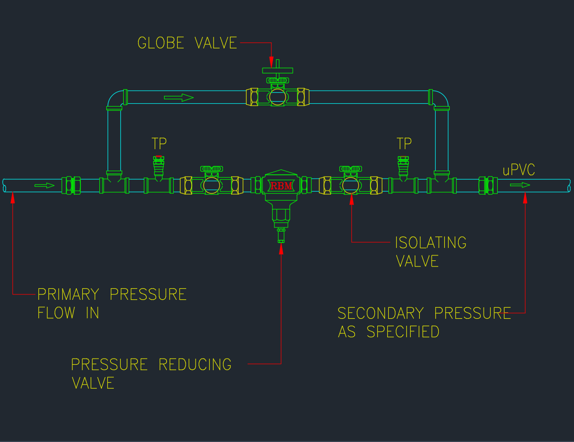
This AutoCAD DWG drawing shows the Pressure Reducing Valve Station Connection Detail, including valves, bypass line, gauges, and piping arrangement.
It’s a standard reference for mechanical, plumbing, and firefighting system designers who need accurate PRV installation layouts.
What Is a PRV Station?
A Pressure Reducing Valve Station controls and maintains downstream water pressure at a predetermined level regardless of upstream fluctuations.
PRV stations are installed in water distribution networks, firefighting risers, and HVAC water systems to protect piping, fittings, and equipment from high-pressure damage.
Typical applications:
- Building main water supply lines
- Fire hydrant and sprinkler systems
- Chilled and hot water distribution
- Irrigation and industrial piping networks
Main Components in PRV Station Detail
| No. | Component | Description |
|---|---|---|
| 1 | Pressure Reducing Valve (PRV) | Automatically reduces water pressure to set outlet value |
| 2 | Inlet & Outlet Isolation Valves | Allow maintenance and valve servicing |
| 3 | Bypass Line with Gate Valve | Provides manual control or maintenance bypass |
| 4 | Pressure Gauges (Inlet & Outlet) | Display water pressure before and after PRV |
| 5 | Strainer | Prevents debris from damaging the valve mechanism |
| 6 | Drain Valve | Allows system flushing and maintenance |
| 7 | Union or Flanged Joint | Enables easy removal for inspection or replacement |
AutoCAD DWG Download
The DWG file includes:
- Plan and section view of PRV station connection
- Complete piping layout with valves and fittings
- Gauge, strainer, and bypass line configuration
- Proper flow direction arrows and annotation layers
Installation Guidelines
- Install PRV station horizontally in accessible area.
- Ensure flow direction matches arrow marking on the valve.
- Provide pressure gauges on both sides for monitoring.
- Install strainer before the PRV for protection.
- Include bypass valve for emergency or maintenance operation.
- Support pipes adequately to prevent vibration and stress.
Applicable Standards
- BS EN 1567 – Building Valves for Water Supply Systems
- NFPA 13 – Fire Sprinkler System Design Standard
- ASHRAE 90.1 / 62.1 – Mechanical System Design
- SMACNA / ASME B31.9 – Piping Installation and Fabrication
Advantages
✅ Protects downstream equipment and fixtures from excessive pressure
✅ Ensures consistent and stable water flow
✅ Reduces risk of leaks and pipe bursts
✅ Extends service life of plumbing systems
✅ Easy maintenance via bypass line and isolating valves
Conclusion
The Pressure Reducing Valve Station Connection Detail is a standard AutoCAD reference for safe and efficient water supply design.
Download the DWG drawing to use in your next MEP or fire protection project for accurate PRV system detailing.