A Pressure Reducing Valve (PRV) is an essential component in water supply and fire protection systems, designed to maintain a consistent downstream pressure regardless of upstream fluctuations.
This post provides a complete AutoCAD DWG file showing the PRV installation detail, typical layout, and connection method for mechanical and plumbing systems.
What Is a PRV (Pressure Reducing Valve)?
A PRV automatically reduces high inlet pressure to a lower, steady outlet pressure.
It protects pipes, fittings, and fixtures from damage caused by excessive pressure and ensures stable water flow in multi-floor buildings.
Common applications include:
- Domestic water supply systems
- Fire fighting networks
- HVAC chilled water loops
- Industrial process piping
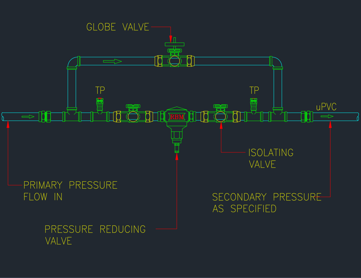
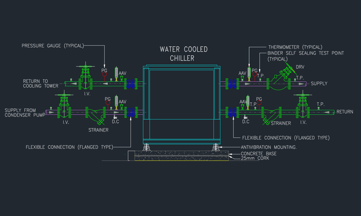
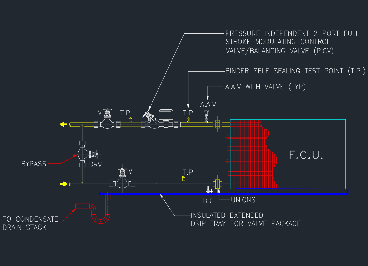
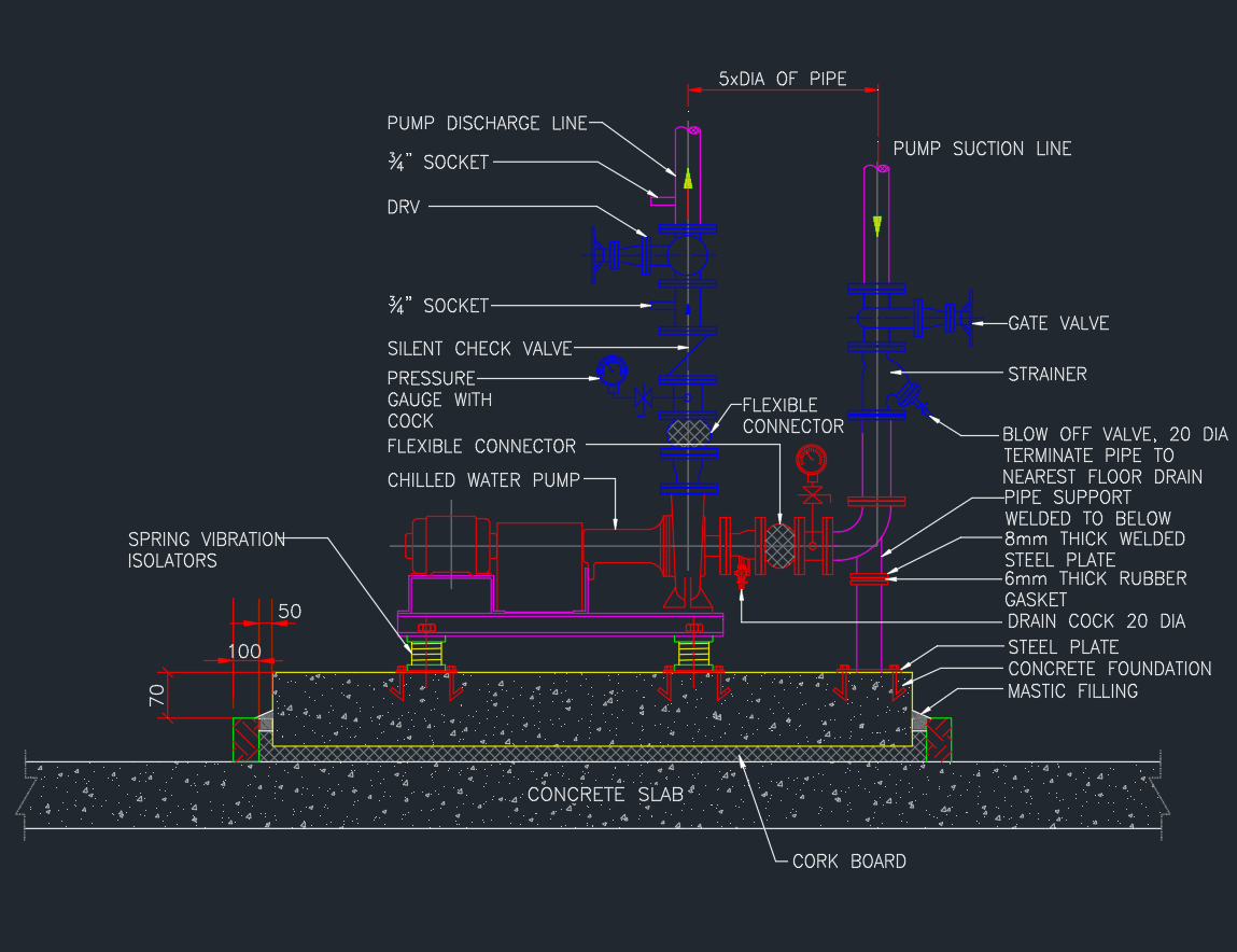
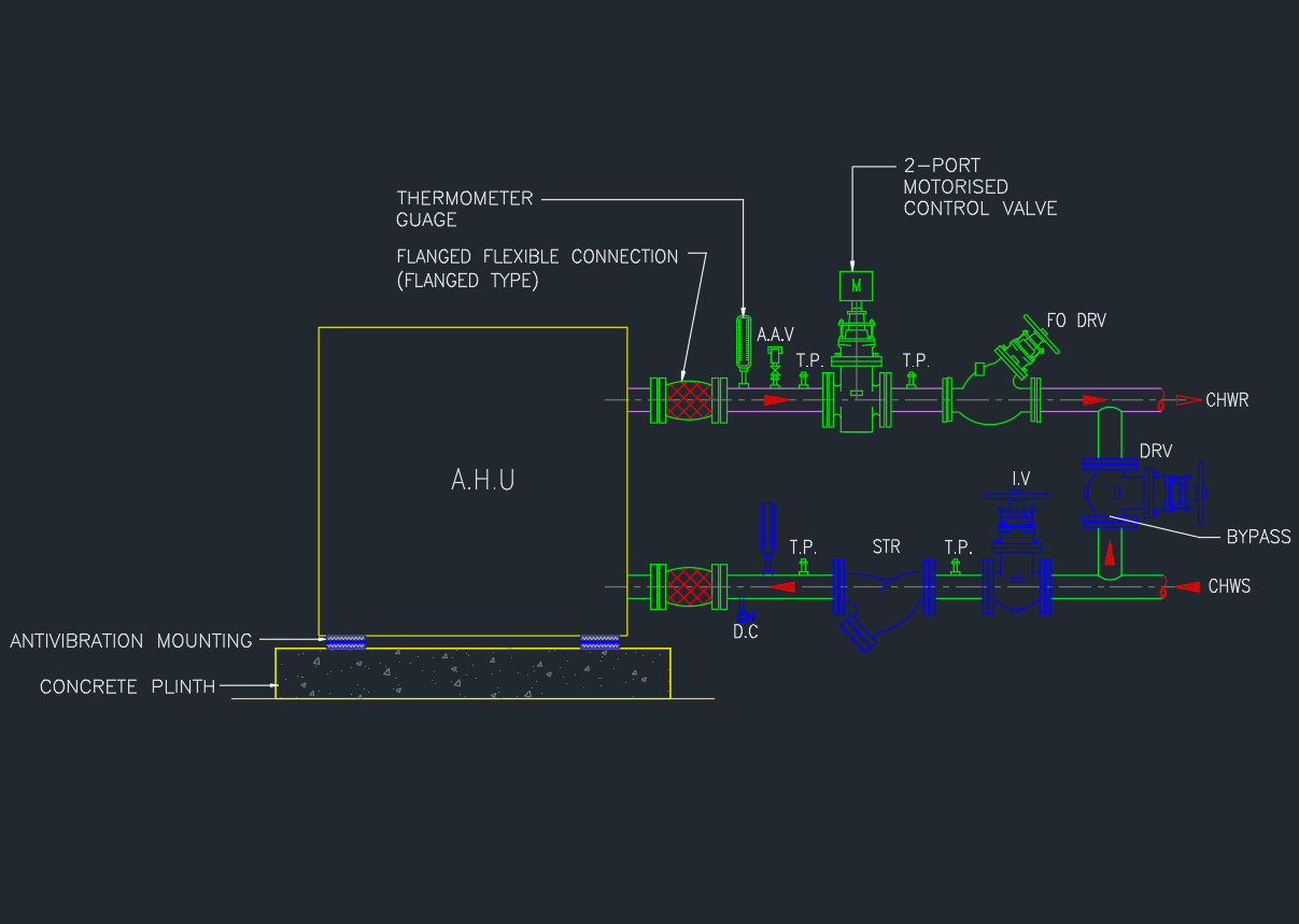
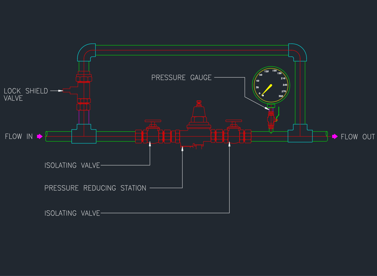
Typical PRV Installation Components
A standard PRV assembly includes:
- Inlet isolation valve (gate or ball valve)
- Strainer (to protect valve from debris)
- Pressure reducing valve (PRV)
- Pressure gauge (inlet/outlet)
- By-pass line with manual valve
- Outlet isolation valve
- Drain valve for maintenance
This arrangement allows for easy service, pressure adjustment, and emergency bypass operation.
PRV Installation Detail – AutoCAD DWG
The downloadable drawing includes:
- PRV assembly layout
- Piping schematic with isolation valves
- Strainer and gauge connection detail
- Typical installation in horizontal and vertical lines
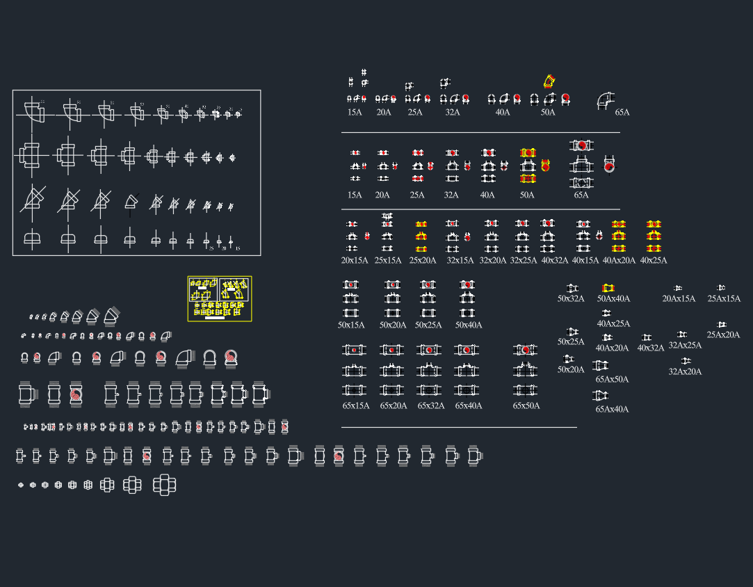
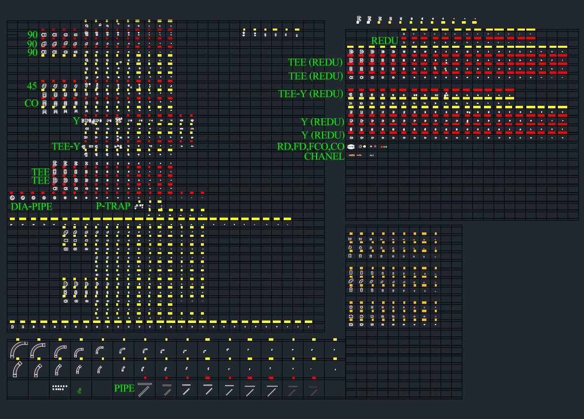
- Legend and symbol reference
Design Guidelines
- Install PRV horizontally for best performance.
- Provide bypass piping for maintenance.
- Place gauges on both sides to monitor inlet and outlet pressures.
- Ensure sufficient clearance for valve removal.
- Follow manufacturer’s direction of flow arrow during installation.
Applicable Standards
- ASME B31.9 – Building Services Piping
- NFPA 13 – Fire Sprinkler System Installation
- BS EN 806-2 – Water Supply Inside Buildings
- ASTM A234 / A105 – Fittings & Flanges
Advantages of PRV Systems
✅ Protects downstream fixtures from over-pressure
✅ Reduces water hammer and noise
✅ Increases lifespan of piping systems
✅ Allows balanced pressure across building zones
✅ Improves energy efficiency of pumping systems
Conclusion
A properly installed Pressure Reducing Valve (PRV) ensures long-term safety and efficiency in plumbing and fire protection systems.
Download the PRV installation detail DWG to include in your next mechanical or MEP project drawing set.