Introduction
Clear power system symbols are essential for communicating how sockets, isolating switches and distribution boards are arranged in a building. In complex residential and commercial projects, a well-structured legend allows engineers, CAD designers and architects to coordinate power layouts with confidence. Using a single DWG legend for all outlet and control symbols improves drawing quality, minimizes site queries and keeps documentation compliant with project standards.
What Are Power System Symbols?
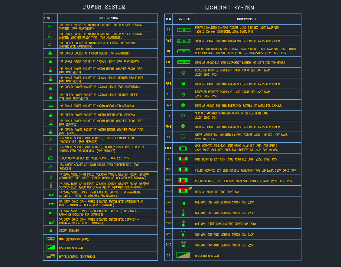
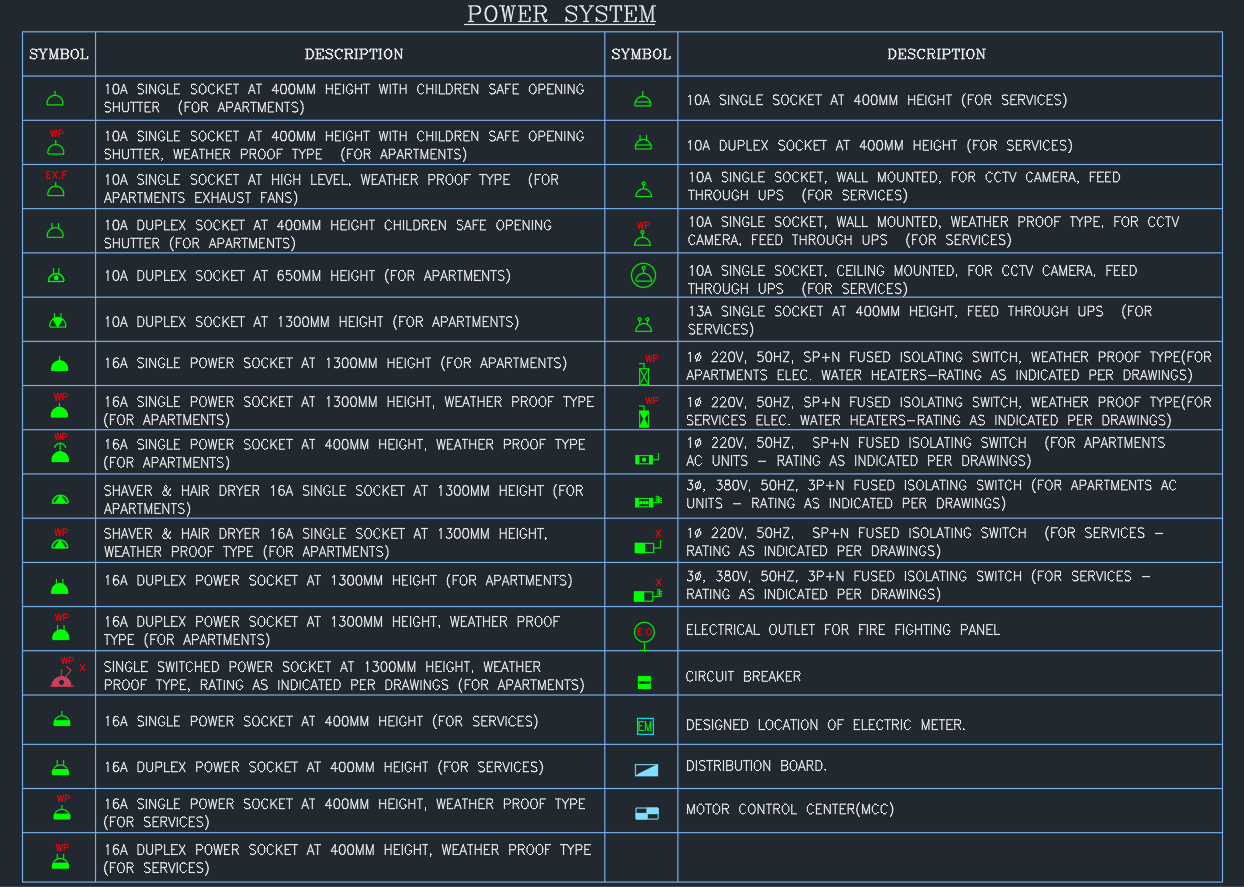
Power system symbols are standardized icons used on electrical plans to represent all power outlets, fused switches and related equipment. The legend typically includes single and duplex sockets, weather proof outlets, UPS-fed sockets, shaver points, isolating switches, distribution boards, circuit breakers and motor control centers.
Each symbol is drawn with a fixed style and linked to a detailed description that explains the height, mounting type and application—for example, “10A duplex socket at 1300 mm height for apartments” or “16A weather proof socket for services”.
Key Socket Symbols in the Legend
Apartment sockets
The legend usually starts with socket symbols for apartments. These include 10A single sockets at 400 mm height with child-safe shutters, duplex sockets at 650 mm and 1300 mm height, and shaver or hair dryer sockets for bathrooms. By defining socket heights and types in the power system symbols legend, designers ensure that electrical layouts respect ergonomic guidelines and local codes.
Service and UPS outlets
Another group of power system symbols covers service areas. Here you will find single and duplex sockets fed through UPS systems for CCTV, access control and communication equipment. Some sockets are wall-mounted, ceiling-mounted or weather proof, depending on their location. Clear differentiation between normal and UPS-fed outlets is crucial for maintaining power to critical systems during outages.
Isolating Switch and Control Symbols
Fused isolating switches
The legend also lists 1φ and 3φ fused isolating switches with specified voltages and ratings. These power system symbols show where water heaters, air-conditioning units and other dedicated loads can be safely isolated. By using consistent icons for isolators, electrical contractors can quickly understand switching points and coordinate cable routes with mechanical services.
Special control and distribution points
Additional symbols may include electrical outlets for fire fighting panels, circuit breaker symbols associated with local control, and designed locations of electric meters. Distribution board and motor control center (MCC) symbols define where main and sub-main panels are located. When combined with distribution panel legends, these power system symbols give a complete picture of how power is distributed throughout the building.
Benefits of a Standard Power System Legend DWG
Using one master DWG file for power system symbols delivers several benefits:
-
Consistency across drawings – every floor plan and schematic uses the same visual language, improving coordination.
-
Faster drafting – CAD users can copy symbols directly from the legend instead of redrawing them.
-
Reduced errors on site – installers clearly understand which socket is normal, weather proof or UPS-fed, and which isolating switch controls each load.
-
Simplified review – consultants, clients and authorities can quickly verify power layouts by referencing a single legend.
For companies that manage multiple projects, maintaining a standard power system legend becomes a key part of their CAD standards library.
How to Use Power System Symbols in AutoCAD
To apply these power system symbols effectively, insert the legend DWG into your template drawing or title sheet at a readable scale. Lock the legend on a dedicated layer so that it cannot be edited accidentally.
When creating layouts, copy the desired symbols from the legend and place them at the correct locations and heights. Use text or attributes to add circuit numbers, load names or UPS references. Avoid inventing new icons during the project; if a new device is required, add it to the legend with a clear description so the entire team can follow the same standard.
Conclusion
A complete set of power system symbols is a small but powerful tool for professional electrical documentation. By standardizing socket outlets, fused isolating switches, distribution boards and MCC symbols in one DWG legend, engineers and CAD designers produce clearer drawings, reduce coordination problems and support safer installations. Whether you work on apartments, services areas or mixed-use developments, a robust power system legend will keep your AutoCAD layouts organized and easy to understand.
⬇ Download AutoCAD File