Introduction
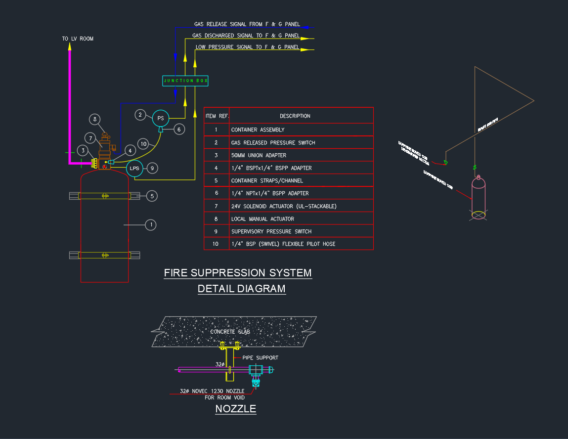
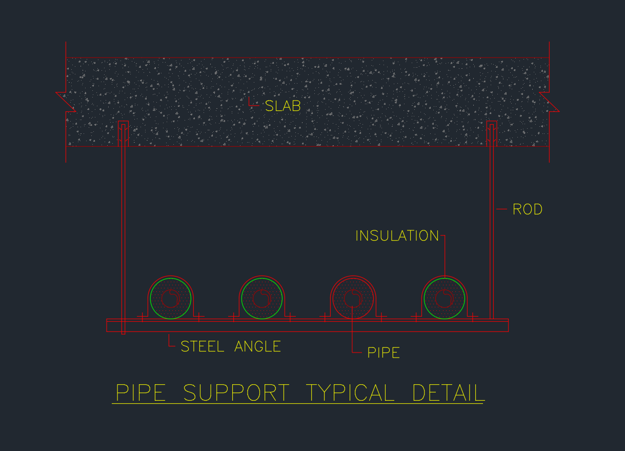
A Pipe Support Typical Detail is a fundamental element in mechanical and plumbing system design. It provides a clear and standardized reference for supporting horizontal pipe runs in HVAC, plumbing, and industrial piping systems. This drawing ensures the structural integrity, alignment, and insulation performance of pipelines under operational conditions.
Pipe supports are essential for maintaining proper spacing, reducing vibration, and preventing mechanical stress on joints and fittings. The detail presented here illustrates a common hanging pipe support system suspended from a concrete slab using rods and steel angles—ideal for HVAC and chilled water piping systems.
Key Components of the Pipe Support Detail
1. Slab
The slab represents the upper structure (usually reinforced concrete) from which the entire pipe support assembly is suspended. It serves as the main anchor point for threaded rods or hanger assemblies. Proper anchoring to the slab is critical to ensure load-bearing capacity and long-term stability.
2. Rod
The rod or hanger rod connects the slab to the supporting steel angle. Typically made from galvanized or stainless steel, these rods are designed to carry the weight of the supported pipes, insulation, and fluids. The rod diameter is selected based on the load and pipe spacing, in accordance with ASME and SMACNA standards.
3. Steel Angle
The steel angle acts as the primary horizontal beam that directly supports the pipes. It is typically fabricated from mild steel or galvanized steel to resist corrosion. The angle size (for example, L50×50×6 mm) depends on the number of pipes, their diameters, and overall weight distribution.
4. Pipe
The pipe represents the fluid conduit—whether chilled water, hot water, or condensate line. It is shown in section view and positioned uniformly along the support. Spacing between pipes is maintained to allow for thermal expansion and ease of insulation installation.
5. Insulation
The insulation layer surrounds the pipe to prevent heat loss or condensation. It plays a vital role in maintaining energy efficiency in HVAC and plumbing systems. The insulation thickness and material (such as elastomeric foam or fiberglass) are determined based on pipe temperature and ambient conditions.
Functional Purpose of Pipe Supports
Pipe supports perform several key functions in building and industrial design:
-
Load Distribution: Evenly transfers the pipe’s weight to the building structure.
-
Alignment Maintenance: Keeps pipes in a precise, horizontal orientation.
-
Vibration Control: Minimizes oscillation caused by fluid flow or mechanical equipment.
-
Thermal Movement Accommodation: Allows controlled expansion and contraction of piping systems.
-
Protection of Insulation: Prevents compression or tearing of insulation material.
Proper pipe support design ensures that the entire piping network remains safe, durable, and efficient over its service life.
Installation and Design Considerations
1. Support Spacing
Support spacing varies with pipe diameter and material. For example, smaller copper or PVC pipes require closer spacing than large steel pipes. Typical spacing for a 100 mm steel pipe is around 3 meters, but designers should consult standards such as ASME B31.1 or MSS SP-58.
2. Vibration and Noise
For HVAC systems, adding vibration isolators or neoprene pads between the steel angle and pipe clamps can reduce noise transmission.
3. Corrosion Protection
Where supports are installed in humid or outdoor environments, galvanized steel or epoxy-coated components are recommended to extend service life.
4. Accessibility
Designers must ensure enough clearance below and around the support for maintenance or insulation replacement.
5. Fireproofing and Safety
In fire-rated zones, supports must be compatible with fireproof coatings or sleeves to comply with mechanical code requirements.
Applications of Pipe Support Typical Detail
This drawing is commonly used in:
-
HVAC systems – Chilled water supply/return, condensate drain lines
-
Plumbing systems – Hot/cold water and sanitary drain lines
-
Fire protection systems – Fire sprinkler pipe hangers
-
Industrial facilities – Process piping and compressed air lines
Including this DWG detail in your project ensures consistency and accuracy during construction, helping engineers and drafters maintain professional documentation standards.
Conclusion
The Pipe Support Typical Detail is a vital reference for mechanical, plumbing, and HVAC engineers. It provides clarity on how pipes are mounted, supported, and insulated within a structure. By using standardized AutoCAD drawings, designers can enhance coordination between architectural and MEP disciplines while ensuring compliance with mechanical design codes.
⬇ Download AutoCAD File