Introduction
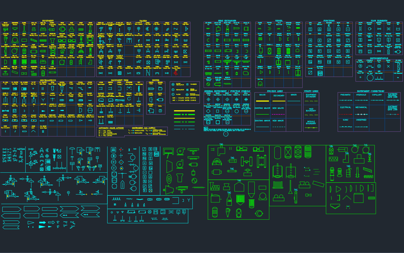
A Piping and Instrumentation Diagram (P&ID) is a detailed schematic showing how process equipment, piping, valves, and instruments are interconnected.
Every component is represented by a standardized symbol that helps engineers, designers, and operators understand the system’s design and control logic.
This guide summarizes the most common P&ID symbols used in mechanical, process, and instrumentation drawings, following ISA-S5.1 / ISO 10628 standards.
1. What Are P&ID Symbols?
P&ID symbols are graphical representations of mechanical and control components in a process system.
They are used to:
- Simplify complex piping systems
- Maintain consistency across drawings
- Communicate design intent to engineers, fabricators, and operators
Each symbol is tagged with a unique identification code (tag number) — for example:
- PIT-101: Pressure Indicator Transmitter
- FV-203: Flow Control Valve
- TIC-301: Temperature Indicator Controller
2. Common Categories of P&ID Symbols
a) Equipment Symbols
Used to show major process machinery and vessels.
| Equipment | Symbol Description |
|---|---|
| Pump | Centrifugal, reciprocating, or screw types |
| Compressor | Centrifugal, screw, or reciprocating compressor |
| Heat Exchanger | Shell & tube, air cooler, plate type |
| Reactor / Vessel | Cylindrical tank with inlet/outlet |
| Storage Tank | Fixed roof, floating roof, or pressurized |
| Filter / Separator | Drum or vessel with filter element |
| Condenser / Evaporator | Cooling or heating unit symbol |
🧩 These symbols help identify equipment connections and maintenance points on your P&ID drawings.
b) Valve Symbols
Valves control the flow of fluid in process lines. The symbol shape indicates type and operation.
| Valve Type | Common Symbol / Description |
|---|---|
| Gate Valve | Straight line with rectangle gate |
| Globe Valve | Spherical outline |
| Ball Valve | Circle with solid fill |
| Butterfly Valve | Circle with diagonal line |
| Check Valve | Arrow with flap symbol |
| Pressure Relief Valve (PSV) | Spring-loaded symbol on line |
| Control Valve | Diaphragm symbol with actuator |
| Solenoid Valve | Control valve with coil marking |
🔧 Control valves include details like actuator type (pneumatic, electric) and fail position (open/closed).
c) Instrumentation Symbols
Instrumentation symbols show sensors, transmitters, controllers, and indicators.
They follow ISA S5.1 standards.
| Instrument Function | Symbol Shape | Example Tag |
|---|---|---|
| Indicator | Circle with single line | PI-101 |
| Transmitter | Circle with double line | PT-101 |
| Controller | Circle with inner cross | PIC-301 |
| Recorder | Circle with diagonal line | TR-201 |
| Computer / PLC | Circle with hexagon border | DCS-401 |
| Shared Display | Circle with dashed border | FIT-201 |
🧠 The first letter indicates the variable (P, T, F, L), and the second indicates function (I, T, C, R, etc.).
d) Piping & Connection Symbols
These define how process lines and utilities are connected.
| Symbol | Description |
|---|---|
| Solid Line | Process Line |
| Dashed Line | Pneumatic or Hydraulic Line |
| Dotted Line | Electrical or Signal Line |
| Arrowhead | Flow Direction |
| Double Line | Jacketed or Insulated Line |
| Triangle Tee | Instrument Connection |
| Break Mark | Line continuation between drawings |
e) Control Loop Symbols
Control loops describe relationships between sensors, controllers, and actuators.
Typical tags and connections:
- TIC-101 → TCV-101: Temperature control loop
- LIC-201 → LV-201: Level control loop
- FIC-301 → FCV-301: Flow control loop
- AIC-401 → AV-401: Analyzer control loop
Each control loop is represented as a closed system connecting measurement → controller → final element.
f) Electrical & Utility Symbols
Used for supporting systems like power, air, and steam.
| Symbol | Function |
|---|---|
| ⚡ | Electrical power connection |
| 🔘 | Ground / Earth |
| 💨 | Instrument Air supply |
| 🔥 | Steam or heating medium |
| 💧 | Cooling water or condensate |
3. P&ID Tagging Convention (ISA Standard)
| Variable | Letter | Example |
|---|---|---|
| Flow | F | FIT-101 |
| Pressure | P | PIT-102 |
| Temperature | T | TIC-103 |
| Level | L | LIT-104 |
| Analyzer | A | AIT-105 |
| Control Valve | CV | FCV-101 |
| Motor Operated Valve | MOV | XV-201 |
| Pressure Safety Valve | PSV | PSV-301 |
Tag numbers typically follow this format:
[Function Letter] [Loop Number] [Device Type] — for example: TIC-301 means Temperature Indicator Controller in loop 301.
4. P&ID Legend and Notation
Every engineering drawing should include a P&ID Legend Table that explains:
- Line types (solid, dashed, dotted)
- Symbols for valves, instruments, fittings
- Color or code used for process vs. utility lines
- Revision number and sheet reference
💡 Always keep your legend consistent across all P&ID sheets for easy reference during HAZOP, design, or commissioning.
5. Download P&ID Symbol Library (DWG)
You can download a complete set of AutoCAD P&ID Symbols for:
- Valves (ball, gate, butterfly, PSV, control)
- Pumps and compressors
- Instruments (pressure, flow, temperature, level)
- Heat exchangers and vessels
- Piping and connection lines
Each symbol is drawn to AutoCAD scale, layer-sorted, and fully editable for project use.
Conclusion
A well-designed P&ID symbol set ensures clarity, consistency, and accuracy in your process drawings.
Whether you’re drafting a chemical plant, gas skid, or water treatment system, standardized symbols are the universal language between design, fabrication, and operations.