Introduction
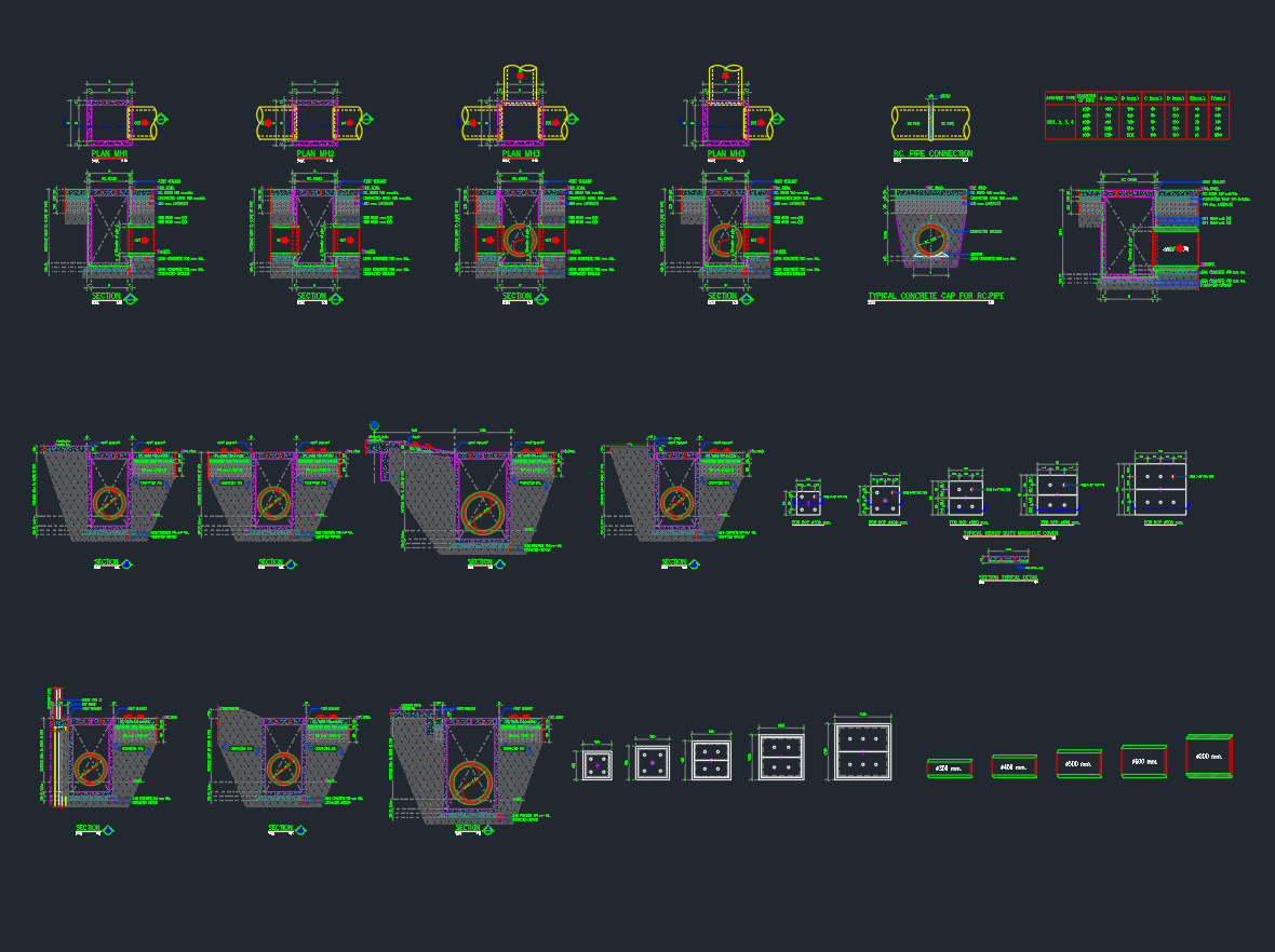
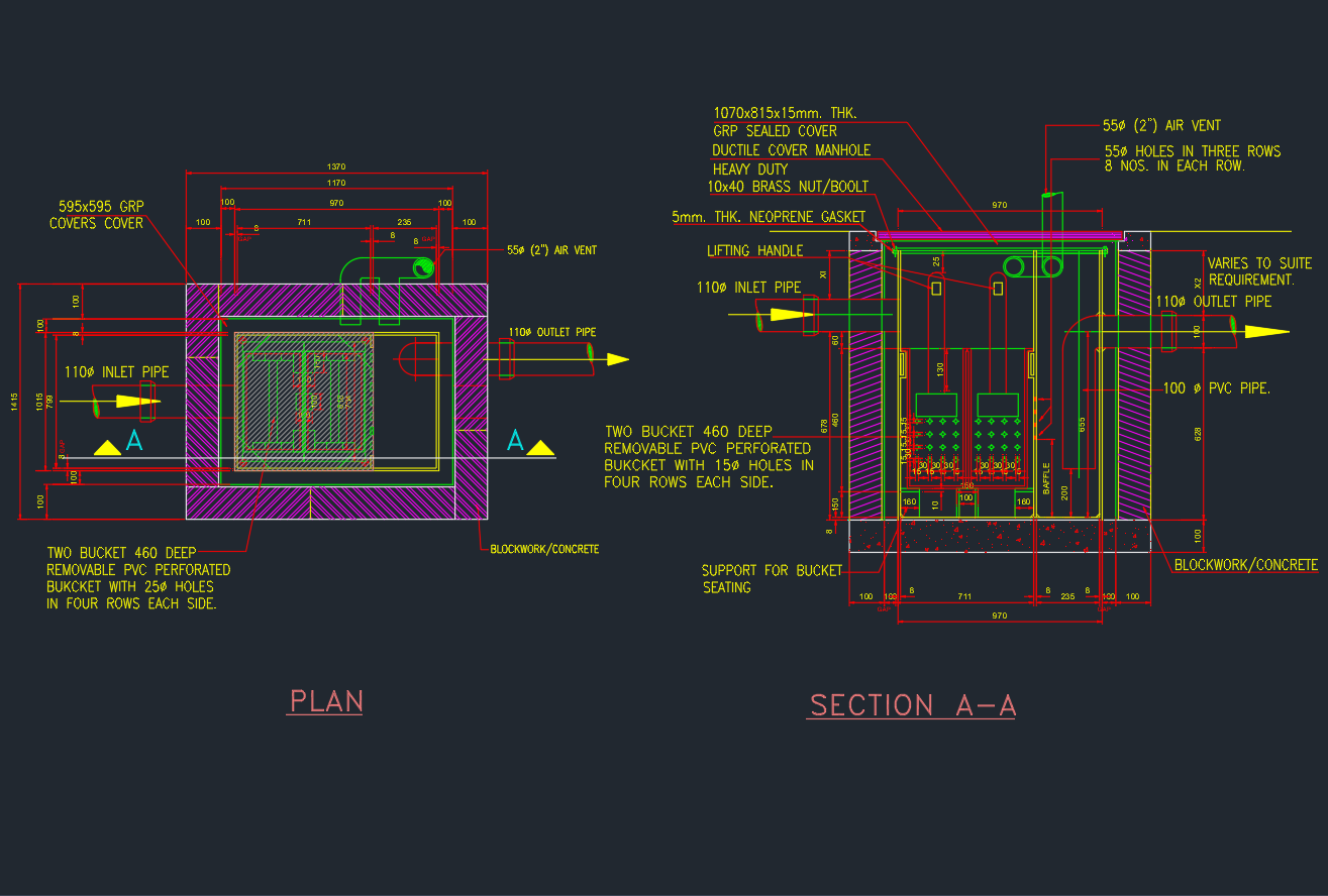
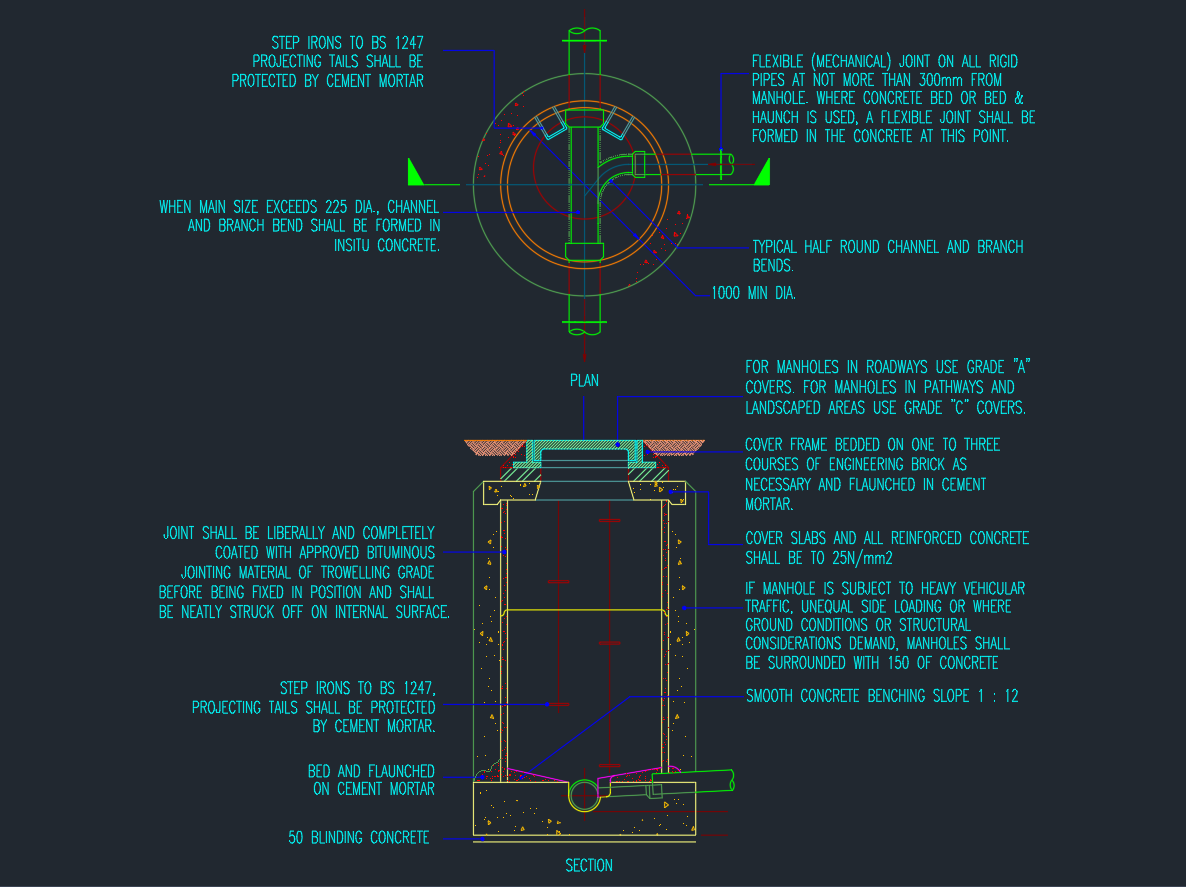
This Manhole Details CAD Drawing (DWG) provides a comprehensive design layout for sewer and stormwater manholes, including plan and sectional views.
It is essential for civil engineers, infrastructure designers, and architects working on drainage or wastewater projects.
The drawing follows BS 1247 standards and includes all necessary specifications for concrete strength, reinforcement, cover types, and construction methodology.
1. Drawing Overview
| Feature | Description |
|---|---|
| File Type | DWG (AutoCAD 2007+) |
| Category | Civil / Infrastructure / Drainage |
| Views | Plan and Section |
| Scale | 1:20 |
| Units | Metric (mm) |
The DWG includes manhole chamber, benching slope, step iron arrangement, and cover slab details for construction reference.
2. Key Components
🧱 Manhole Structure
-
Reinforced concrete wall and slab (25N/mm² grade)
-
Smooth benching slope (1:12)
-
50mm blinding concrete base
-
Step irons to BS 1247 standard
-
Bituminous jointing material at all connections
🚰 Pipe Connections
-
1000 mm minimum internal diameter
-
Flexible mechanical joints on all rigid pipes
-
Typical half-round channel and branch bends
-
Pipe entry sealed and haunched with cement mortar
🪨 Cover & Frame
-
Grade A covers for roadways
-
Grade C covers for landscaped areas
-
Cover frame bedded on 1–3 courses of engineering bricks
-
Flunched and cemented for structural stability
3. Design Notes
✅ Use bituminous jointing material of trowelling grade.
✅ Flexible joints to be formed within 300mm of the manhole wall.
✅ Reinforced concrete cover slabs must withstand vehicular loading when in roadways.
✅ For unequal ground conditions, surround with 150mm concrete.
✅ Ensure step irons are coated with cement mortar to prevent corrosion.
4. Applications
-
Sewer and drainage systems
-
Urban stormwater networks
-
Infrastructure and utility projects
-
Water treatment plant layouts
-
Road and pathway drainage design
5. Download Manhole Detail DWG
File Size: ≈ 100 KB
License: Free for personal and educational use
Conclusion
This Manhole CAD Drawing is an essential reference for civil engineers and AutoCAD designers involved in drainage and wastewater design.
With clearly labeled construction and reinforcement details, it ensures compliance with engineering standards and site safety requirements.
⬇ Download AutoCAD File💧 Download now to enhance your civil CAD drawing library with complete manhole design details.