Introduction
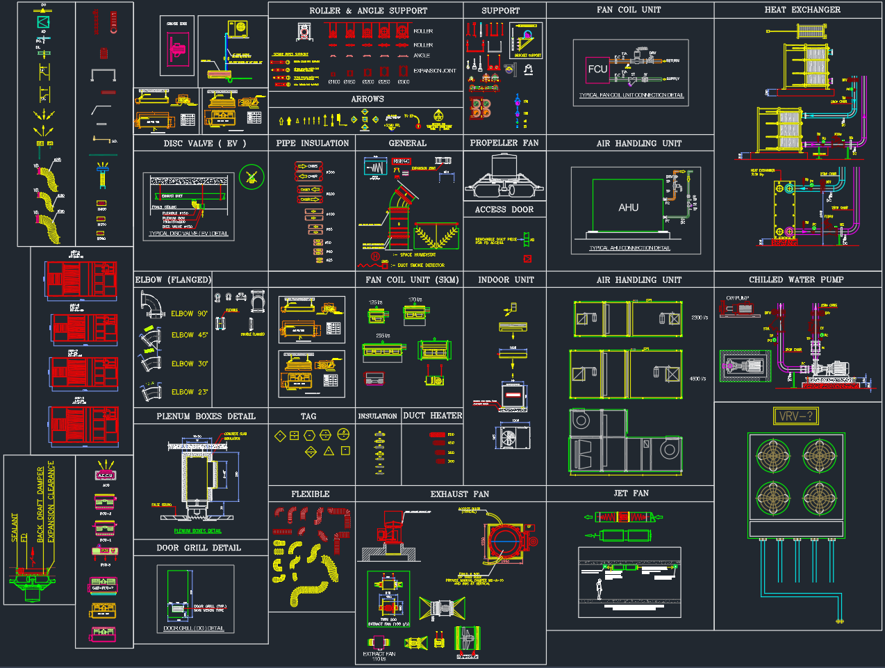
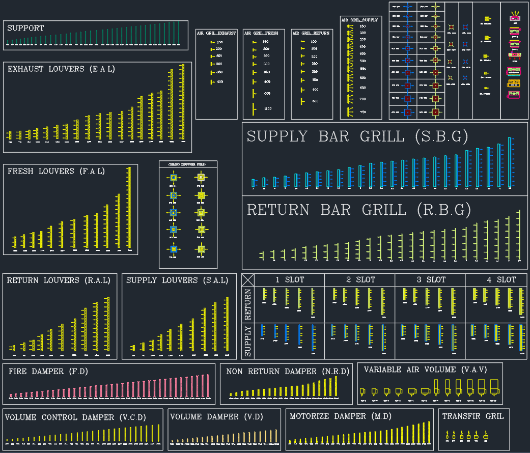
The HVAC Grill and Louver DWG file provides a complete library of air distribution components for mechanical engineers, architects, and MEP designers. This AutoCAD collection includes supply and return air grilles, diffusers, louvers, and dampers, drawn to standard HVAC drafting conventions for professional design documentation.
It is ideal for MEP layout plans, mechanical system coordination drawings, and HVAC tender submissions.
Components Included in the DWG
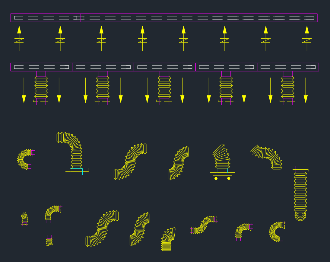
1. Supply and Return Bar Grilles (S.B.G / R.B.G)
-
Standard linear slot and bar-type grilles for ceiling or wall mounting.
-
Available in 1-slot to 4-slot configurations for different air volume requirements.
-
Each block includes accurate airflow direction arrows (supply or return).
-
Ideal for connecting to flexible ducts, FCUs, and air plenums.
2. Louvers
Louvers regulate airflow and protect against dust, water, and debris. This DWG includes several categories:
-
Fresh Air Louvers (F.A.L): For outdoor air intake systems.
-
Exhaust Air Louvers (E.A.L): For ventilation exhaust or fan discharge.
-
Supply Air Louvers (S.A.L): For wall-mounted supply systems.
-
Return Air Louvers (R.A.L): For low-velocity return air applications.
Each louver symbol is drawn in progressive size variations (150 mm – 600 mm) with frame and blade details, following SMACNA and ASHRAE guidelines.
3. Dampers
Control and safety components included in the drawing:
-
Volume Control Damper (V.C.D): For regulating airflow in duct branches.
-
Motorized Damper (M.D): Electrically controlled for automation systems.
-
Non-Return Damper (N.R.D): Prevents backflow in exhaust ducts.
-
Fire Damper (F.D): Includes fusible link detail for fire-rated ducts.
-
Variable Air Volume (V.A.V) Boxes: For zone temperature control and dynamic airflow balancing.
Each damper type includes an identifiable symbol and mechanical actuation orientation (manual, electric, pneumatic).
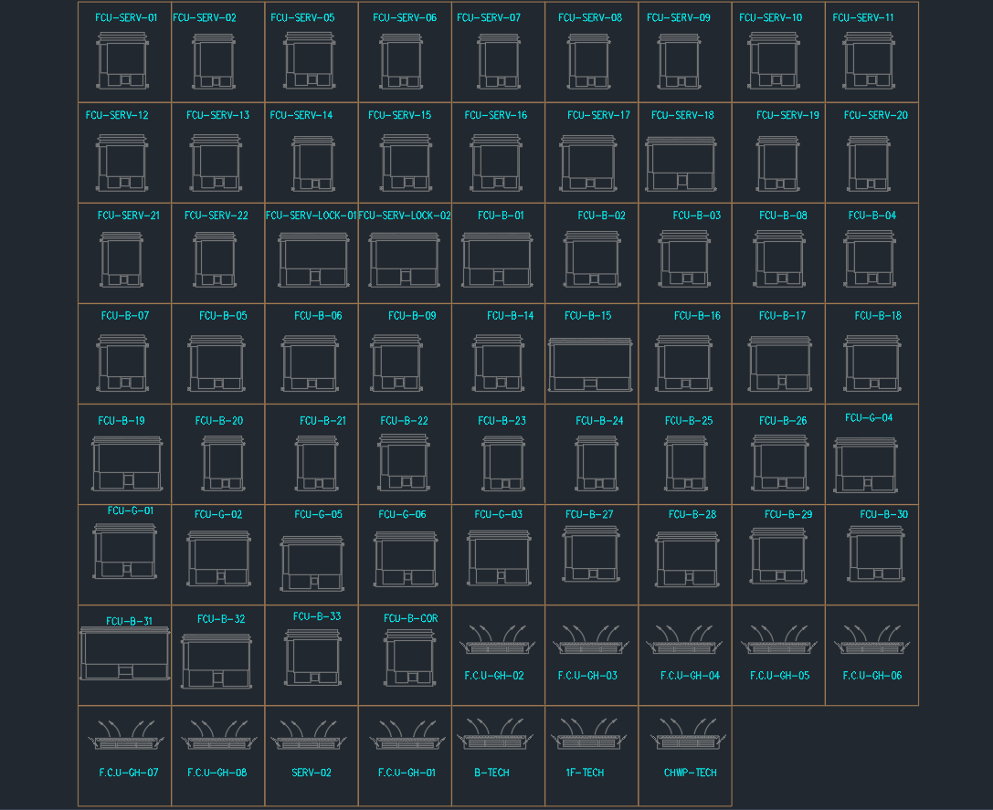
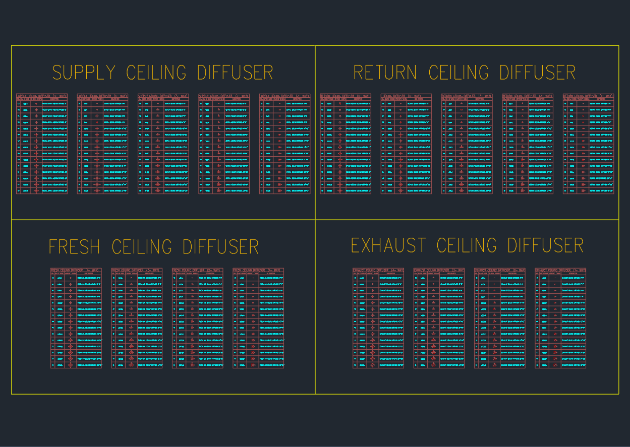
4. Diffusers and Ceiling Outlets
-
Square and Circular Diffusers: Suitable for ceiling supply layouts.
-
Slot Diffusers (1–4 Slot): For linear air distribution in commercial spaces.
-
Transfer Grilles: For cross-room air balancing.
-
Plenum Box Detail: Included for connecting diffusers to flexible ducts.
5. Support and Accessories
-
Hanger and frame support details for grille mounting.
-
Tag symbols for airflow direction, diffuser identification, and damper labeling.
-
Section details of ceiling grille installation and air passage alignment.
Technical Specifications
| Parameter | Details |
|---|---|
| File Format | AutoCAD DWG |
| View Type | 2D plan, elevation, and detail |
| Compatibility | AutoCAD 2007 and newer |
| Standard Reference | ASHRAE / SMACNA / DW/144 (Ductwork Standards) |
| Scale | 1:1 (fully editable) |
| Organization | Layered by component type (SUPPLY, RETURN, LOUVER, DAMPER) |
| Usage | HVAC design, documentation, and coordination drawings |
Applications
This HVAC Grill and Louver DWG file is ideal for:
-
HVAC System Layouts – Air distribution and return system planning.
-
MEP Coordination Drawings – Integration with ducts and structural ceilings.
-
Air Terminal Design – Diffuser and grille layout for mechanical tender documentation.
-
Fire & Smoke Protection – Damper and louver detailing in safety systems.
-
Architectural Finishes Coordination – Matching grille types with interior design.
Design and Installation Notes
-
Grille Spacing: Maintain uniform spacing to ensure even air distribution.
-
Damper Integration: Install dampers near supply branches for maintenance access.
-
Air Velocity: Keep below 2.5–3.0 m/s in return ducts to reduce noise.
-
Fire Dampers: Place at fire-rated wall or floor penetrations as per NFPA 90A.
-
Ceiling Integration: Coordinate diffuser and louver placement with lighting fixtures.
Benefits
✅ Comprehensive HVAC Air Terminal Set – All essential grills, louvers, and dampers in one DWG file.
✅ Professional Layout-Ready Symbols – Standardized to industry norms.
✅ High Clarity and Layer Organization – For easy visibility control in AutoCAD.
✅ Time-Saving Design Resource – Ready for use in mechanical layouts and tender submissions.
✅ Editable and Scalable – Adjust line weight, color, and annotation for any project standard.
Conclusion
The HVAC Grill and Louver DWG library is a complete solution for professionals designing air distribution systems in AutoCAD. It provides ready-made blocks for supply, return, and exhaust air terminals, along with damper and diffuser details, helping you produce precise, professional mechanical drawings.
Perfect for MEP engineers, HVAC consultants, and drafting specialists, this DWG file ensures your air terminal design complies with both functional and architectural requirements.
⬇ Download AutoCAD File