Introduction
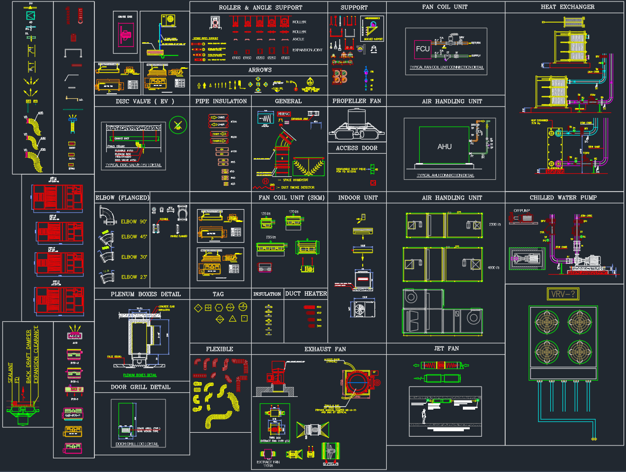
This HVAC Equipment DWG file provides a complete set of AutoCAD blocks for heating, ventilation, and air conditioning systems. It includes detailed 2D symbols and schematic layouts for AHUs, FCUs, chillers, fans, pumps, and ducts, following standard mechanical and MEP drafting conventions.
Designed for engineers, architects, and CAD designers, this drawing is ideal for HVAC system planning, coordination drawings, and construction documentation.
Main Categories in the DWG File
1. Air Handling Units (AHU)
The file includes floor plan and schematic details of Air Handling Units showing:
-
Casing dimensions and internal components
-
Filter section, cooling coil, and fan arrangement
-
Duct inlet/outlet connections
-
Motor drive and vibration isolator details
These AHU blocks are suitable for both single-zone and multi-zone air systems.
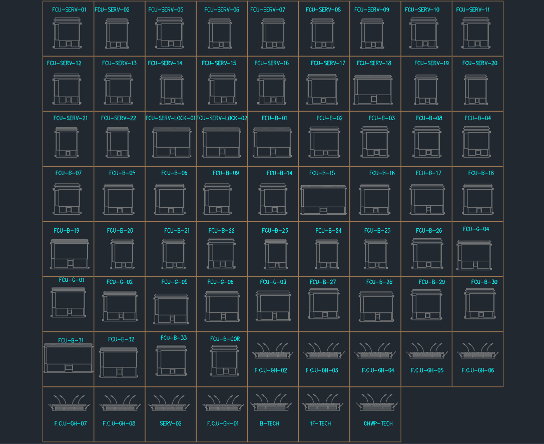
2. Fan Coil Units (FCU)
Includes wall-mounted, floor-standing, and concealed ceiling-type FCUs with piping and valve connections.
-
Supply and return air connections
-
Condensate drain line layout
-
Valve and actuator assembly details
Each FCU block is scaled for easy placement in architectural layouts and mechanical plans.
3. Chilled Water Pump and Piping Layout
This section shows typical chilled water pump connections with valves, strainers, and flexible joints.
-
Primary and secondary pump systems
-
Suction and discharge piping details
-
Pressure gauge and isolation valve positions
-
Base frame and anchor support drawings
4. Heat Exchangers
Detailed DWG blocks of plate and shell-type heat exchangers include:
-
Piping arrangement
-
Insulation details
-
Mounting supports and connections to chilled or hot water systems
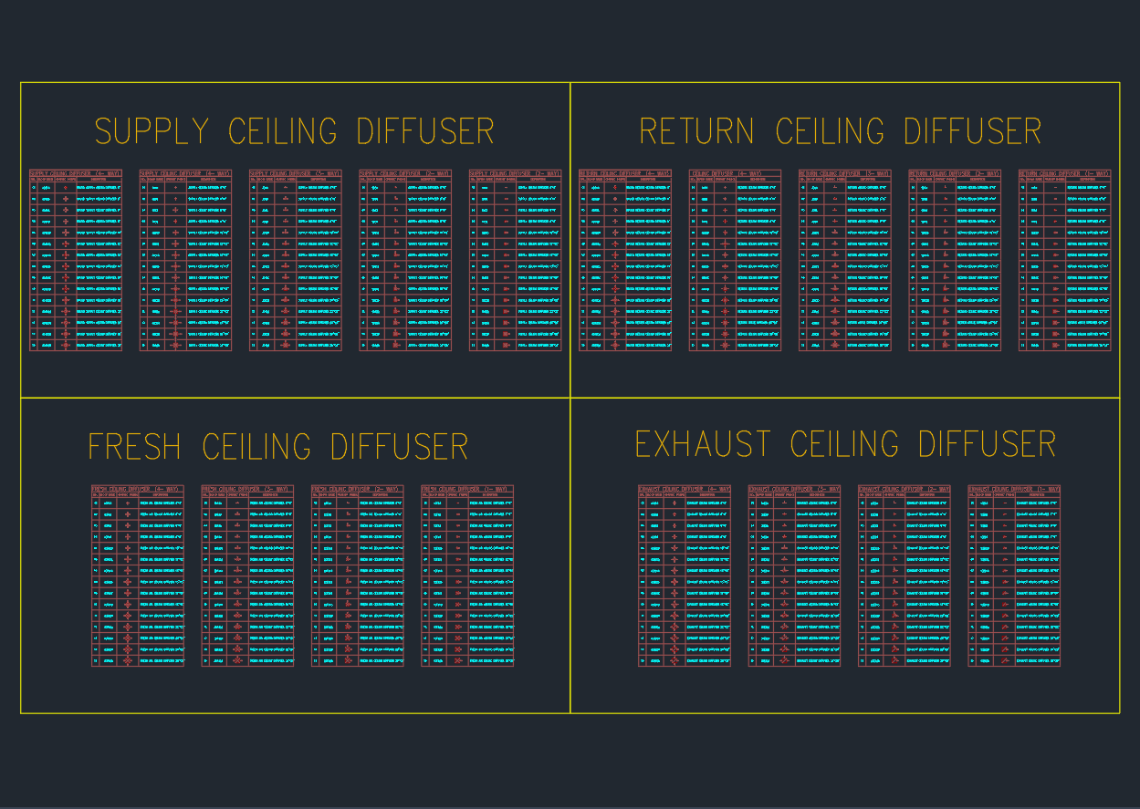
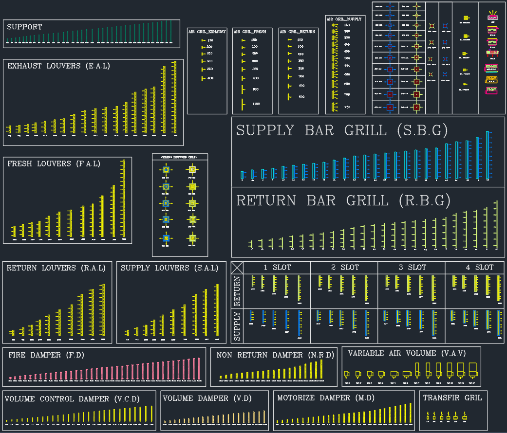
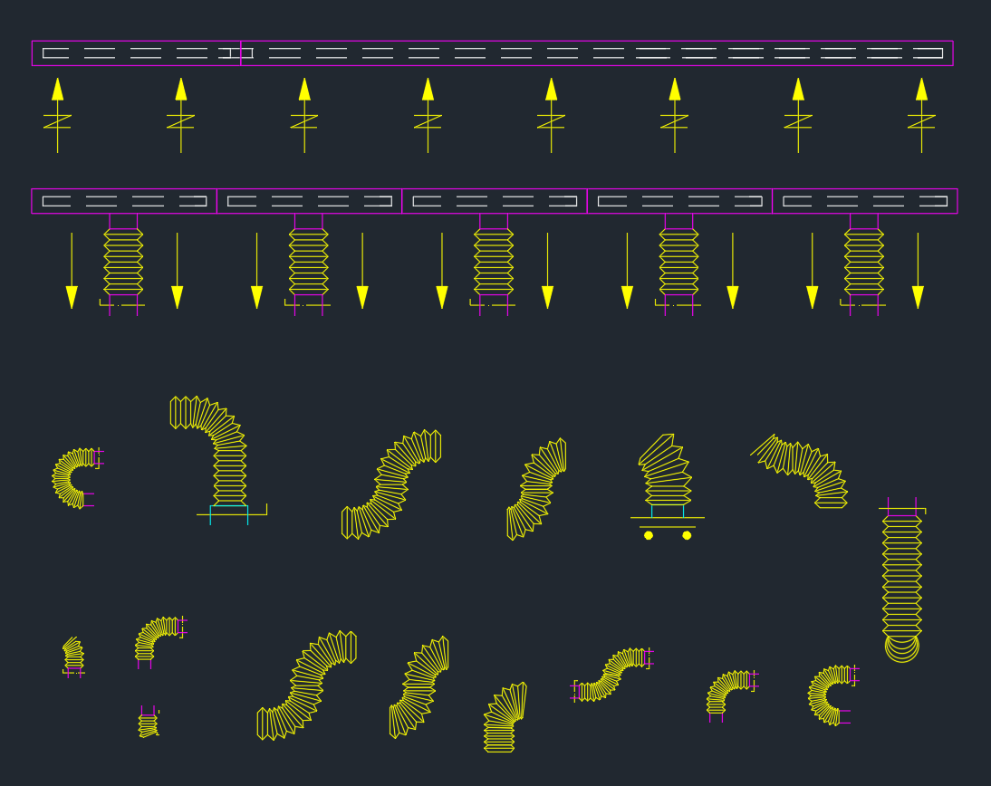
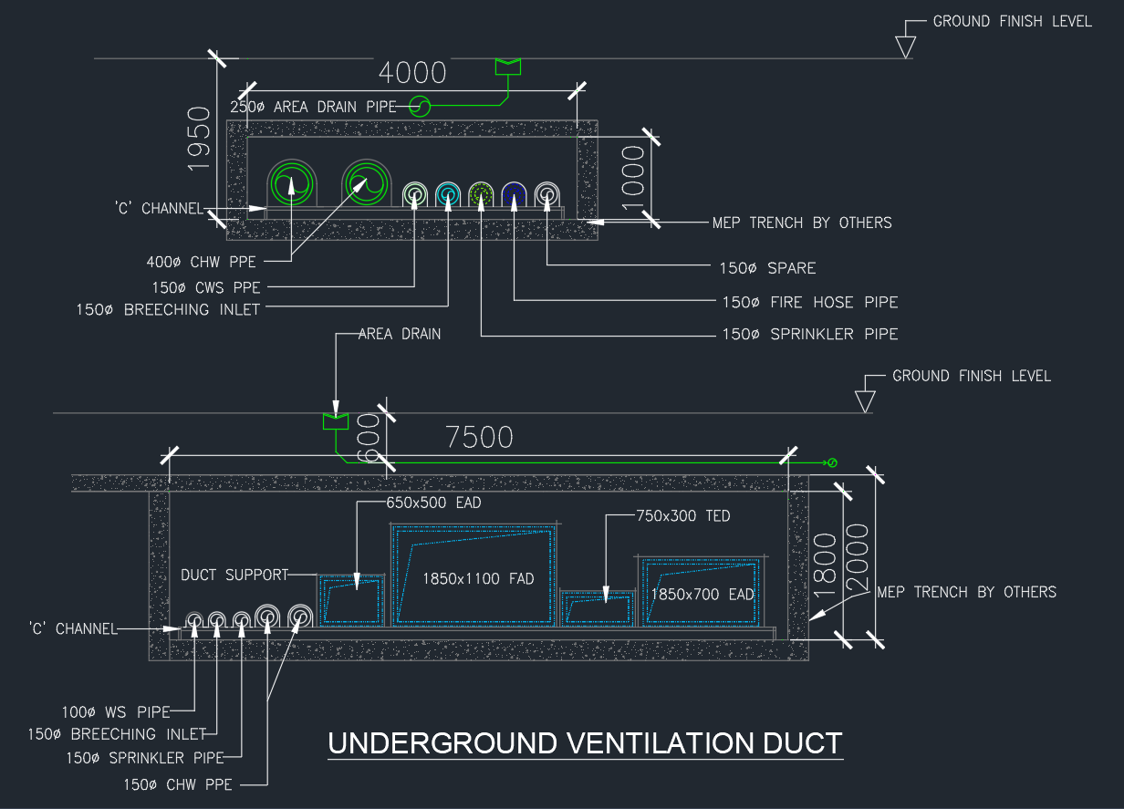
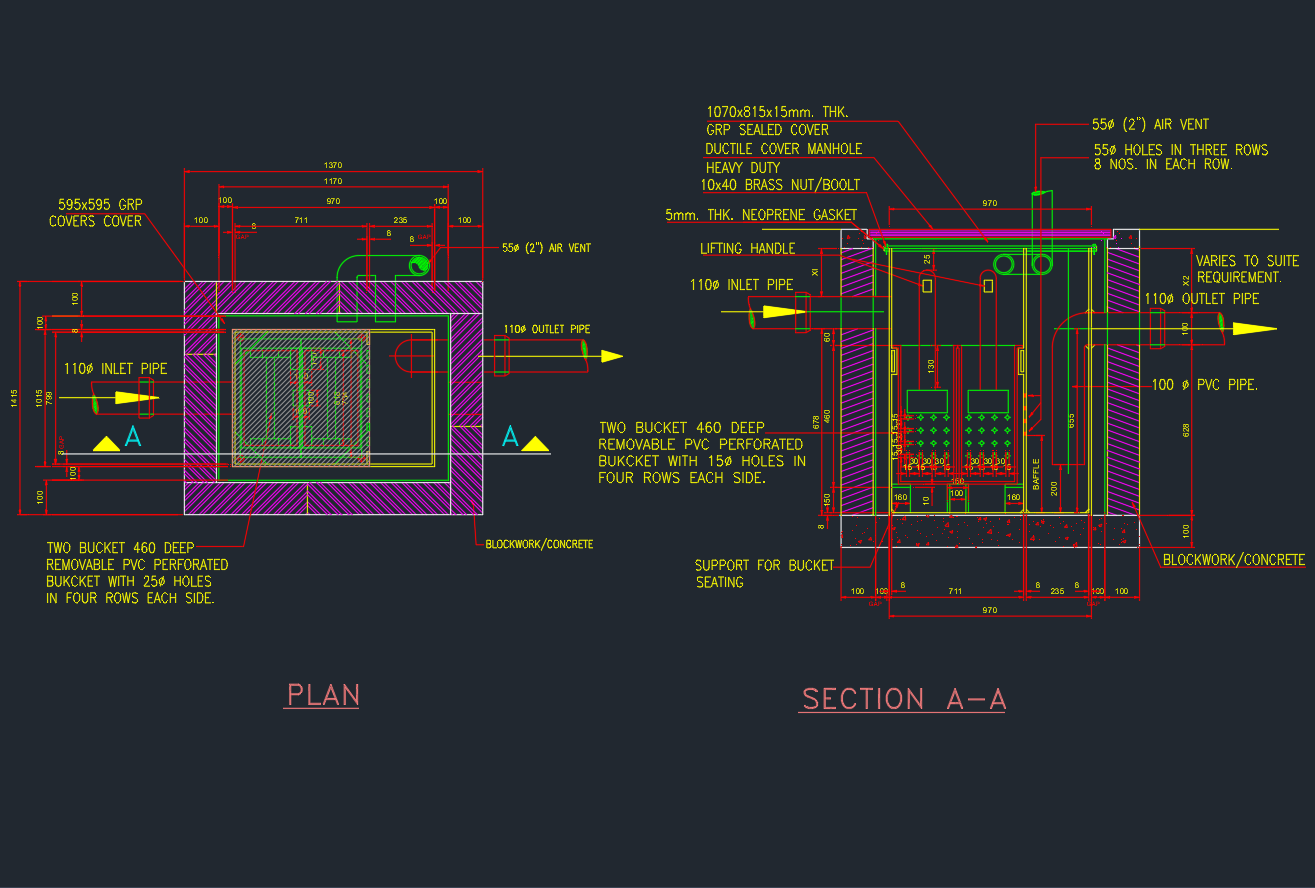
5. Ventilation and Duct Accessories
A comprehensive library of duct system components, such as:
-
Elbows (flanged and slip joint types) – 30°, 45°, and 90°
-
Flexible duct connectors
-
Jet fans and propeller fans
-
Exhaust fans and air grilles
-
Plenum boxes and diffusers
Each item is drawn with installation and section details suitable for construction drawings.
6. VRV/VRF System Layouts
Includes Variable Refrigerant Volume (VRV) and Variable Refrigerant Flow (VRF) system diagrams:
-
Outdoor condensing unit with multiple indoor units
-
Refrigerant pipe routing and joint connections
-
Condensate drain and power control cable schematics
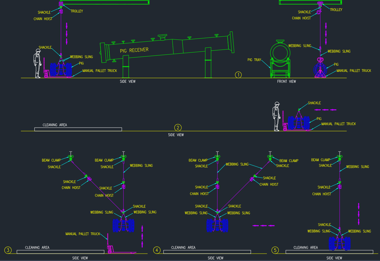
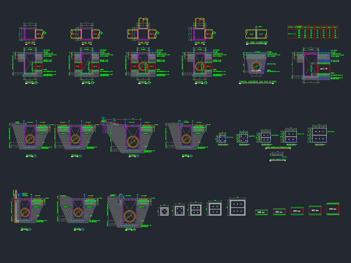
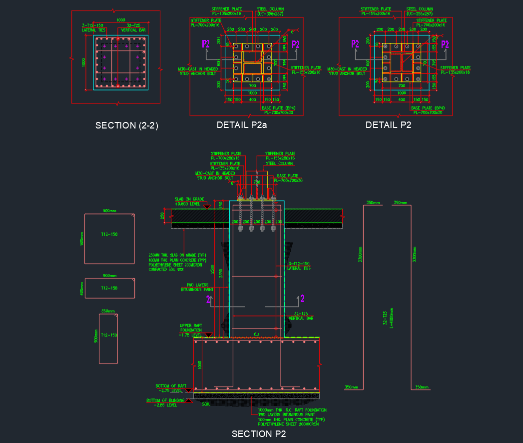
7. Support and Installation Details
The file also provides standard support and hanger details for MEP coordination:
-
Roller and angle supports for horizontal ducts and pipes
-
Pipe hangers with insulation clamps
-
Seismic restraint details for duct and piping systems
-
Access doors and service openings
File Specifications
| Parameter | Description |
|---|---|
| File Format | AutoCAD DWG |
| View | 2D plan, elevation, and schematic |
| Scale | 1:1 (realistic scaling) |
| Compatibility | AutoCAD 2007 and newer |
| Layering | Organized by component type (AHU, DUCT, FAN, PIPE, etc.) |
| Standard | ASHRAE / SMACNA reference for HVAC components |
| Editable | Fully explodable and customizable |
Applications
This HVAC DWG Equipment Library is useful for:
-
MEP Coordination Drawings – Clash-free layout planning across disciplines
-
HVAC System Design – Chilled water, VRF, and air distribution systems
-
Mechanical Tender Drawings – Equipment selection and layout submissions
-
Construction Detailing – Fabrication-level coordination and shop drawings
Advantages
-
Comprehensive Resource – Contains all essential HVAC components in one file.
-
Time-Efficient – Pre-drawn blocks reduce drafting time and improve accuracy.
-
Professional Standards – Complies with ASHRAE and SMACNA drafting conventions.
-
Customizable Layouts – Easy to edit, rescale, or modify according to project requirements.
-
Clear Documentation – Organized by equipment type and system function for quick reference.
Drawing Highlights
-
Air Handling Unit Layouts – Plan and section details with filter and coil arrangements
-
Fan Coil Unit Details – Ceiling and floor-mounted configurations
-
Chilled Water Pump System – Pump connection schematics and isolation valve setups
-
Elbow and Duct Fittings – Various angles with flanged connections
-
Heat Exchanger Arrangement – Plate and shell-type with detailed sections
-
Plenum and Grill Details – Section and isometric views for air distribution fittings
Conclusion
The HVAC Equipment CAD Blocks DWG file is an all-in-one AutoCAD resource for designing mechanical and air-conditioning systems. With detailed symbols for AHUs, FCUs, chillers, fans, duct fittings, and piping, this drawing helps engineers and designers produce accurate, well-coordinated mechanical layouts.
Perfect for building services engineers, MEP consultants, and contractors, this DWG library ensures your HVAC documentation meets professional and international standards.
⬇ Download AutoCAD File