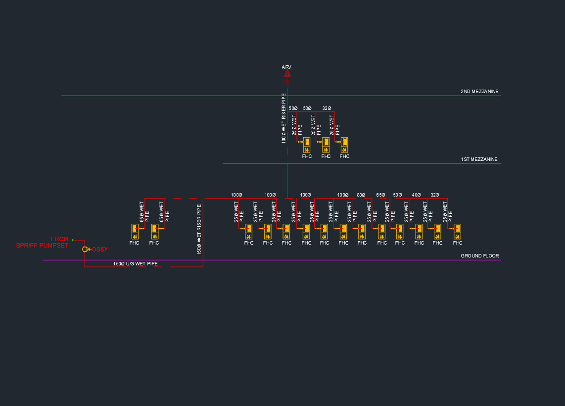
The Hose Reel System Schematic Diagram provides a complete AutoCAD layout showing how water is distributed from the main supply to each hose reel in a fire protection network. This DWG drawing illustrates essential components such as gate valves, pressure gauges, flow switches, isolation valves, and hose reel cabinets. It serves as an important reference for engineers, fire safety designers, and contractors when planning or inspecting wet riser and hose reel systems in commercial or residential buildings. Download this AutoCAD hose reel schematic drawing to ensure accurate design, compliance with fire safety codes, and efficient system operation.
⬇ Download AutoCAD FileHose Reel System Schematic Diagram | AutoCAD Drawing