CAD Blocks Hub for Industrial Design

Your Source for Engineering CAD Blocks & Typical Drawings

Gas System Schematic Diagram AutoCAD Drawing

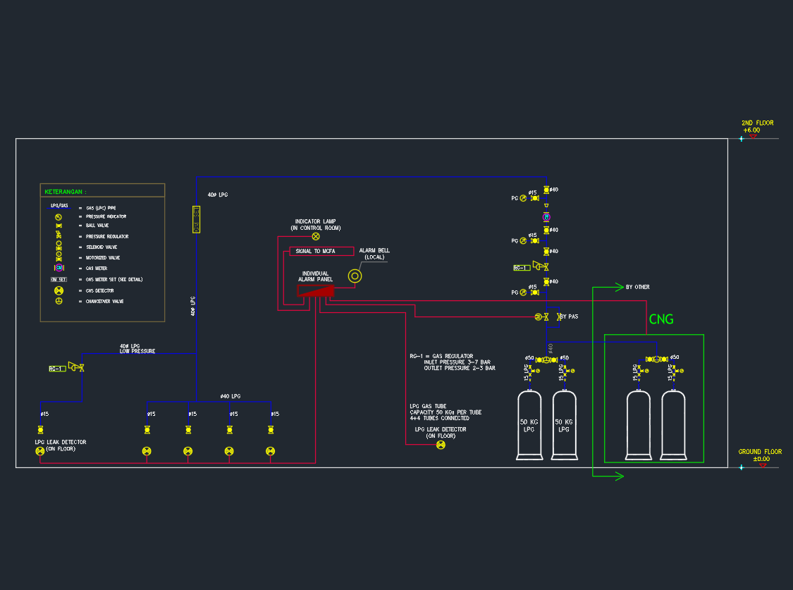
The Gas System Schematic Diagram AutoCAD Drawing provides a complete and accurate representation of gas supply and distribution layouts used in residential, commercial, and industrial projects. This DWG file shows the connection of gas meters, regulators, valves, and pipelines — helping engineers and designers ensure safety, flow balance, and compliance with standards. Ideal for MEP engineers, gas system designers, and contractors, this drawing assists in planning efficient gas routing and installation. Download this gas system schematic AutoCAD DWG to enhance your design documentation, support safety compliance, and improve coordination in mechanical projects.

⬇ Download AutoCAD File
Share This:

More posts

  • Door Key Access for Security and Architectural Design
  • Pressure Reducing Valve Station for Water Supply System
  • Pumping Chamber Detals for Drainage and Water Supply Systems
  • Detail of Dosing Pot Connections – AutoCAD Drawing
  • Chiller Piping Connection Detail | AutoCAD Drawing
  • Typical Detail of FCU Connections – AutoCAD Drawing
  • Chilled Water Pump Foundation Detail | Drawing for HVAC System
  • Typical Detail of AHU Chilled Water Piping Connection
  • Pressure Reducing Valve (PRV) Installation Detail | for Plumbing System
  • Galvanized Steel Pipe (GSP) and Fittings | AutoCAD Drawing
  • PVC Fitting Pack for Plumbing AutoCAD Drawings
  • Mechanical Symbol | AutoCAD MEP DWG Drawing