Introduction
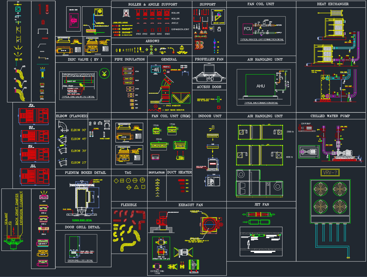
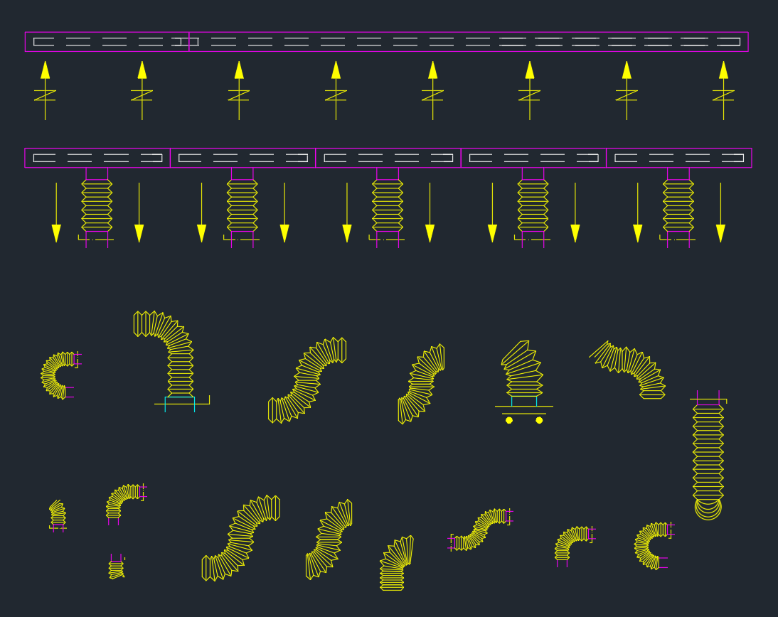
A Flexible Duct is a vital component of modern HVAC systems, providing versatile air distribution connections between diffusers, grilles, and main duct lines. This AutoCAD DWG file includes detailed 2D blocks of flexible duct layouts in various configurations — straight, curved, horizontal, and vertical — commonly used in residential, commercial, and industrial air systems.
These blocks are perfect for mechanical engineers, HVAC designers, and MEP drafting professionals who need precise, ready-to-use details for air distribution systems.
Drawing Overview
The DWG file contains multiple flexible duct configurations optimized for schematic, layout, and detailed HVAC drawings.
1. Straight Flexible Ducts
-
Aligned with main duct lines for ceiling air distribution.
-
Includes both supply and return air flow directions with standard arrow indicators.
-
Ideal for connecting rectangular duct trunks to air diffusers or grilles.
2. Vertical Drop Ducts
-
Represent flexible duct connections dropping from ceiling ductwork to diffusers or fan coil units.
-
Includes top and side views for clear installation guidance.
3. Curved and Bent Duct Sections
-
Includes 30°, 45°, and 90° curved flexible duct blocks.
-
Used for routing ducts around obstacles or within ceiling voids.
-
Drawn with realistic segmented geometry to indicate flexibility and bend radius.
4. Offset and Twisted Duct Configurations
-
Shows complex layouts where ducts must offset between equipment and diffusers.
-
Useful for VRF/VRV systems or tight ceiling spaces requiring custom routing.
5. Support and Connection Details
-
Includes flange, collar, and clamp connection symbols.
-
Shows interface between flexible ducts and rigid sheet-metal ducting.
-
Compatible with diffuser and grille detail drawings.
Technical Specifications
| Parameter | Description |
|---|---|
| File Format | AutoCAD DWG |
| Drawing Type | 2D HVAC ductwork |
| Scale | 1:1 (realistic geometry) |
| Line Type | Polyline segments with smooth bends |
| Compatibility | AutoCAD 2007 and newer |
| System Type | Supply air, return air, and exhaust ducting |
| Standard Reference | ASHRAE / SMACNA HVAC Drafting Standard |
| Editing | Fully explodable and layer-adjustable |
Typical Applications
This Flexible Duct DWG library is widely used in:
-
HVAC System Layouts – Connecting diffusers, FCUs, and AHUs.
-
Mechanical Coordination Drawings – Ceiling-level routing and clash-free installation planning.
-
Construction Shop Drawings – Detailing flexible duct lengths and connection types.
-
VRF/VRV System Design – Linking indoor units to main refrigerant and air lines.
Design Considerations
-
Maximum Length: Flexible ducts should not exceed 1.5–2.0 meters to minimize pressure losses.
-
Bend Radius: Avoid sharp bends; maintain at least duct diameter × 2 as a minimum radius.
-
Support Spacing: Provide mechanical support every 1.2–1.5 meters.
-
Airflow Direction: Always indicate airflow arrows for clarity during coordination.
-
Insulation Type: Use thermally insulated flexible ducts for conditioned air systems.
Advantages of Using This DWG Library
✅ Ready-to-Use Blocks: Pre-drawn and standardized for HVAC layouts.
✅ Professional Detailing: Includes both plan and side views.
✅ Time-Saving: Simplifies ductwork routing and documentation.
✅ Customizable: Compatible with any project scale or layer structure.
✅ Ideal for Coordination: Works seamlessly with diffuser, AHU, and FCU drawings.
How to Use in AutoCAD
-
Insert DWG Block – Use
INSERTor drag the flexible duct block into your layout. -
Adjust Scale – Match project unit (metric/imperial).
-
Set Layer – Assign to mechanical or HVAC layer for clarity.
-
Add Flow Arrows – Indicate air direction for coordination with diffuser points.
-
Annotate – Label duct diameter, length, and connection type for shop drawings.
Conclusion
The Flexible Duct CAD Blocks DWG provides all the necessary 2D details to accurately represent flexible air connections in HVAC layouts. From straight runs to curved and vertical sections, this file covers every practical configuration used in real-world projects.
Ideal for mechanical consultants, MEP coordinators, and HVAC fabricators, this DWG set ensures professional-quality drafting and compliance with standard HVAC detailing practices.
⬇ Download AutoCAD File