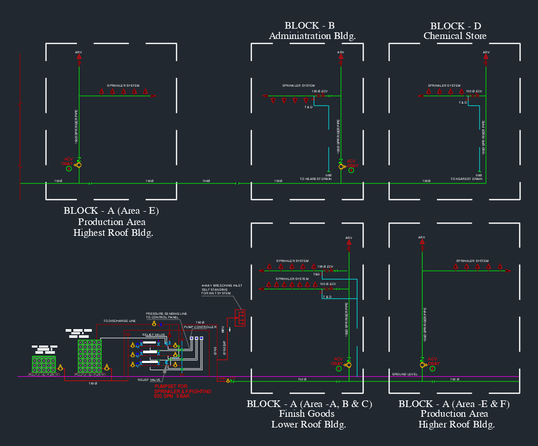
The Schematic Diagram for Fire Sprinkler System provides a complete AutoCAD representation of how water is distributed throughout a building’s fire suppression network. This DWG drawing shows all key components — including alarm check valves, pressure gauges, flow switches, test drains, and sprinkler heads — clearly arranged for design and maintenance reference. It helps engineers, MEP designers, and contractors ensure correct system configuration, pressure balance, and NFPA code compliance. Download this fire sprinkler schematic AutoCAD drawing to improve your fire protection design accuracy and documentation for commercial, residential, or industrial building projects.
⬇ Download AutoCAD FileFire Sprinkler System Schematic Diagram | AutoCAD Drawing