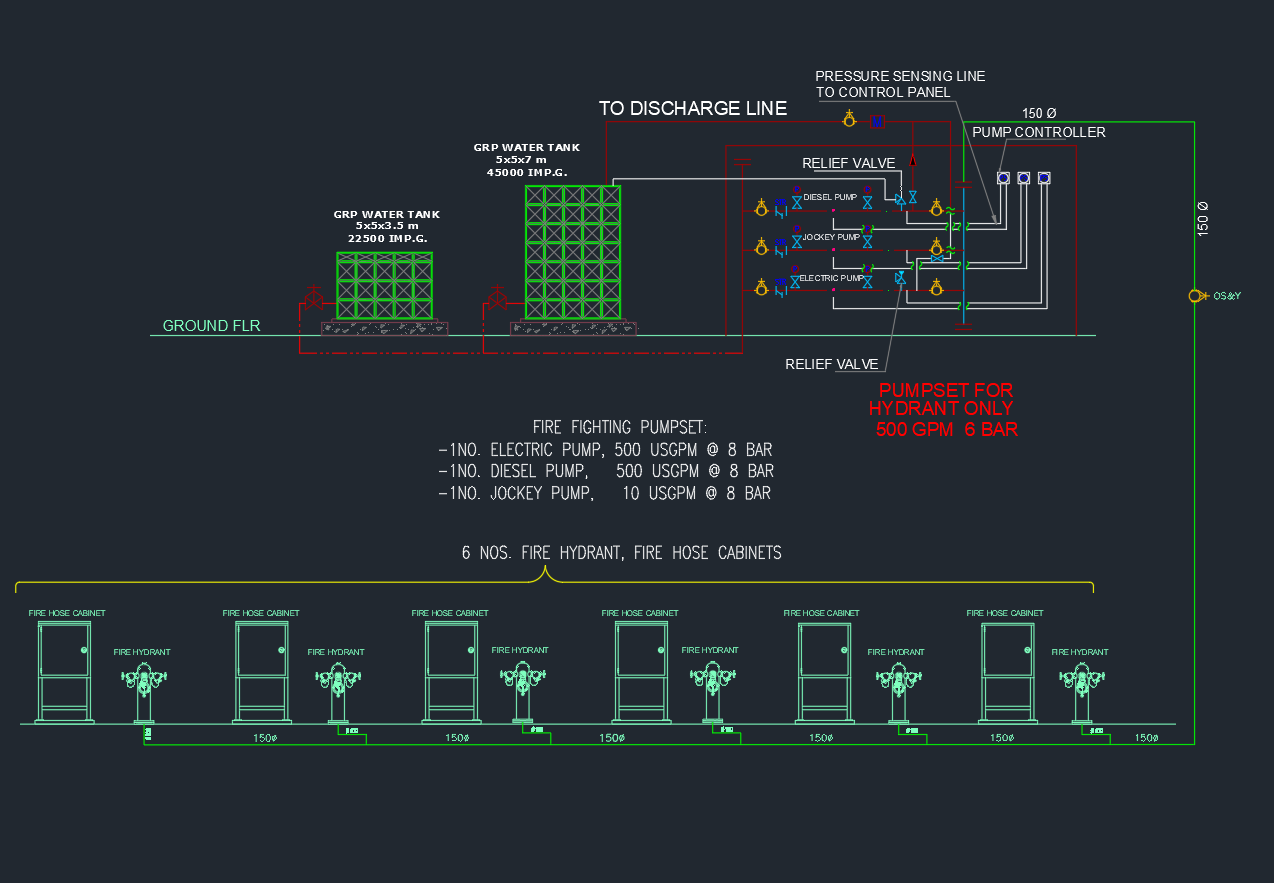
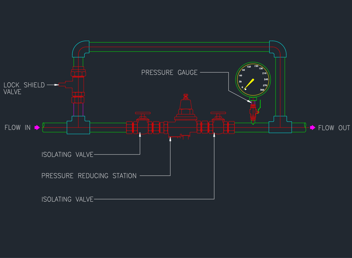
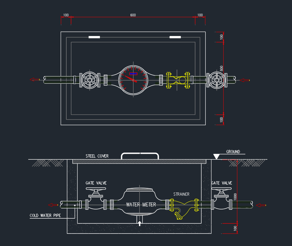
The Schematic Diagram for Fire Hydrant System provides a detailed AutoCAD layout showing the connection of water mains, landing valves, hose cabinets, pumps, and pressure gauges in a fire protection network. This DWG drawing is ideal for MEP engineers, fire safety designers, and contractors who need accurate design references for hydrant installations in buildings or industrial sites. It helps visualize the flow path, system zoning, and pressure distribution to ensure NFPA and local code compliance. Download this fire hydrant schematic AutoCAD drawing to enhance design precision, improve documentation quality, and support reliable fire system planning and inspection.
⬇ Download AutoCAD FileFire Hydrant System Schematic Diagram | AutoCAD Drawing