CAD Blocks Hub for Industrial Design

Your Source for Engineering CAD Blocks & Typical Drawings

Fire Hydrant Pillar Type | Typical Installation Drawing

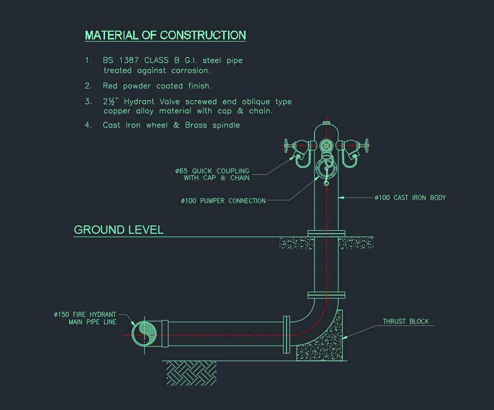
The Typical Installation Details for Fire Hydrant Pillar Type drawing provides a precise AutoCAD layout showing how pillar-type hydrants are installed in fire protection systems. This DWG file includes underground piping connections, valves, thrust blocks, and hydrant outlet dimensions — all crucial for accurate construction and code compliance. Designed for engineers, fire system designers, and contractors, this AutoCAD drawing serves as a reference for civil and MEP coordination. Download this fire hydrant pillar type installation detail DWG to ensure proper system setup, long-term reliability, and compliance with NFPA or local fire safety standards in your project.

⬇ Download AutoCAD File
Share This:

More posts

  • Vibration Isolator AutoCAD Drawing for HVAC Equipment
  • Typical Heat Exchanger Connection Detail AutoCAD Drawing
  • Fresh Air Handling Unit Valve Arrangement AutoCAD Drawing
  • Expansion Tank and Air Separator Piping Diagram AutoCAD Drawing
  • Plate Heat Exchanger AutoCAD Drawing | Detailed Equipment
  • Heat Exchanger AutoCAD Drawing Professional Equipment Design
  • Flexible Joint in AutoCAD Drawing for Piping Systems
  • Check Valve AutoCAD Drawing | Detailed Equipment CAD Files
  • Stop Valve | AutoCAD Piping DWG Drawing
  • Y Type Strainer AutoCAD Drawing | Download Equipment CAD File
  • Double Seated Valve | AutoCAD Mechanical Drawing
  • Butterfly Valve DWG | Free AutoCAD Drawing for Industrial Use