Introduction
A clear Fire Fighting Legend is essential for any building services drawing that includes fire protection systems. When symbols for sprinklers, hose reels, cabinets, valves and extinguishers are standardized in one legend, engineers, CAD designers and architects can coordinate layouts more efficiently and reduce errors on site. This Fire Fighting Legend DWG is designed to support professional fire protection drawings for residential, commercial and industrial projects.
What Is a Fire Fighting Legend?
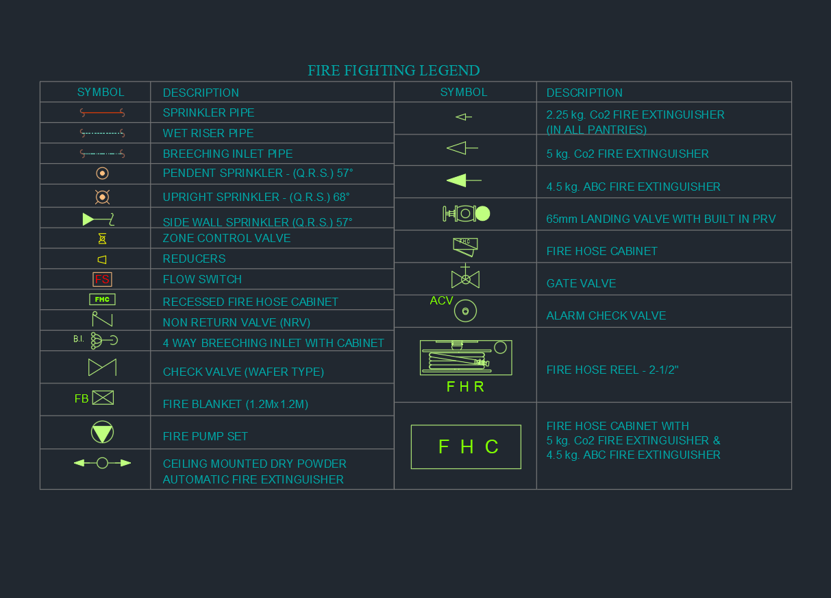
A Fire Fighting Legend is a compact table of CAD symbols and descriptions used on fire protection plans. The legend explains the meaning of each symbol representing sprinkler pipes, wet risers, breeching inlets, zone control valves, fire hose cabinets, fire hose reels, check valves, non-return valves and various types of fire extinguishers.
Instead of repeating long notes across drawings, the Fire Fighting Legend provides a single reference that can be read by all project stakeholders. Fire engineers, contractors and authorities can interpret every symbol quickly, which speeds up design review and approval.
Key Components of the Fire Fighting Legend
Sprinkler network symbols
The Fire Fighting Legend begins with symbols for the sprinkler network. These typically include sprinkler pipes, wet riser pipes and breeching inlet pipes, followed by pendent, upright and side-wall sprinkler heads. Each sprinkler symbol is associated with temperature rating or response characteristics, such as quick response sprinklers at specific angles.
By using these symbols, designers can clearly show head locations, pipe routing and connection points to zone control valves or alarm check valves. This improves coordination with architectural ceilings and structural beams.
Valves and fittings
Another important part of the Fire Fighting Legend is the family of control valves and fittings. Zone control valves, gate valves, alarm check valves, non-return valves and wafer-type check valves are all represented by distinct CAD symbols. Reducers and other fittings may also be included.
These symbols allow engineers to define how each sprinkler zone is isolated, drained and monitored. Consistent valve symbols make hydraulic calculations easier to follow and help contractors understand where flow switches and pressure gauges will be installed.
Hose cabinets and hose reels
Fire hose cabinets and fire hose reels are critical for manual firefighting inside buildings. The Fire Fighting Legend provides symbols for recessed fire hose cabinets, cabinets with integrated extinguishers, and hose reel units with the familiar “FHR” annotation.
Using these standardized symbols ensures that hose cabinets are correctly positioned along escape routes and near exits. It also clarifies cabinet types where multiple extinguishers, hose reels and landing valves share the same enclosure.
Fire extinguishers and special equipment
The legend also lists symbols for various fire extinguishers, such as 2.25 kg CO₂, 5 kg CO₂ and 4.5 kg ABC extinguishers, together with combined fire hose cabinet and extinguisher sets. Additional equipment such as fire blankets, landing valves with built-in PRV and fire pump sets may appear in the same Fire Fighting Legend.
These symbols help designers demonstrate compliance with code requirements for extinguisher type, rating and location. Installers can quickly verify that the correct unit is installed at each symbol on the plan.
Benefits of Using a Standard Fire Fighting Legend DWG
Using a standardized Fire Fighting Legend DWG offers several advantages:
-
Consistency across projects – all drawings use the same symbol set, making it easier for teams to switch between jobs.
-
Faster drafting – CAD users can copy symbols from the legend rather than redraw components for each project.
-
Reduced site errors – contractors and inspectors share a common understanding of sprinkler heads, valves and hose cabinets.
-
Simplified maintenance – facility managers can rely on the legend to identify system components long after construction is complete.
For companies with strict CAD standards, the Fire Fighting Legend becomes a core block in their template files.
How to Use This Fire Fighting Legend in AutoCAD
To use the Fire Fighting Legend effectively, insert the DWG block on your general notes sheet or main fire protection layout. Place it at a scale that is easy to read when plotted. Lock the legend on a dedicated layer so it cannot be deleted or edited accidentally.
When drafting, copy symbols from the Fire Fighting Legend and place them on your plan views and schematics. Align the symbol usage with the descriptions in the legend and avoid introducing new icons without updating the legend. For clarity, keep all fire protection symbols on dedicated layers (for example, sprinklers, pipework, valves, cabinets and extinguishers) so they can be isolated during coordination with other disciplines.
Conclusion
A professional Fire Fighting Legend is a small but powerful asset in any fire protection drawing set. By consolidating sprinkler, valve, hose reel, cabinet and extinguisher symbols into a single DWG file, design teams can create clear, consistent and code-compliant documentation. Whether you are preparing concept layouts or detailed construction drawings, a reliable Fire Fighting Legend will keep your AutoCAD files organized and your fire protection designs easy to understand.
⬇ Download AutoCAD File