Introduction
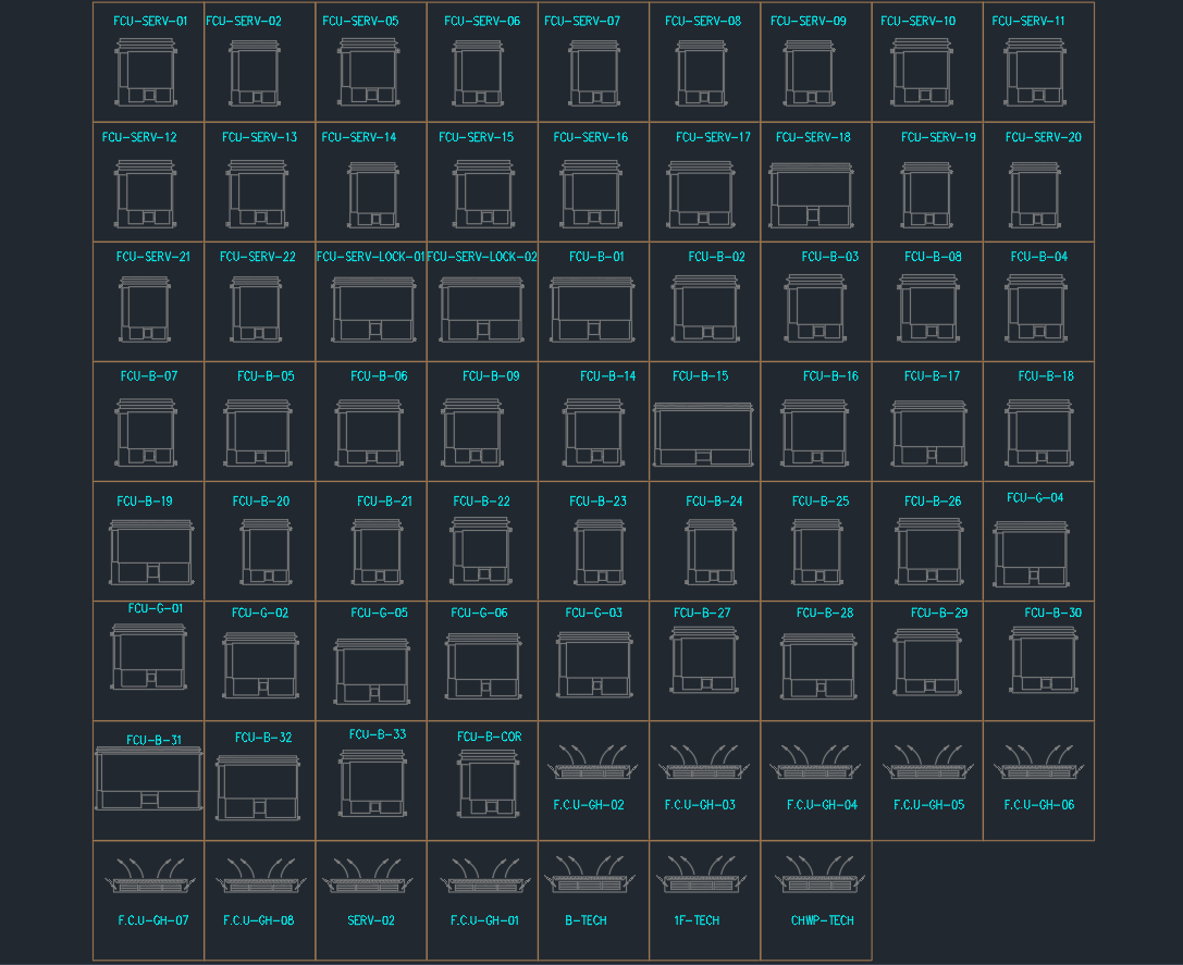
The Fan Coil Unit (FCU) DWG file provides a complete set of AutoCAD blocks for HVAC mechanical layouts. These CAD drawings include front, side, and airflow views of horizontal, vertical, and ceiling-mounted FCUs, ideal for professional MEP, design coordination, and construction documentation.
This library represents realistic mechanical configurations typically used in brands like YORK, Carrier, Daikin, and Trane, and is suitable for architects, HVAC engineers, and contractors working on chilled water or DX systems.
Drawing Overview
The DWG file contains multiple FCU series organized by function and installation type:
1. FCU–SERV Series (Service Units)
-
Represent standard ceiling-concealed horizontal FCUs.
-
Includes 20+ variations labeled FCU–SERV–01 to FCU–SERV–22.
-
Used for suspended ceiling spaces in offices, hotels, or commercial buildings.
-
Each block shows coil housing, fan section, and condensate drain line.
2. FCU–B Series (Basic Ceiling Models)
-
Compact FCUs with coil and fan section detailing.
-
Includes FCU–B–01 to FCU–B–33.
-
Suitable for two-pipe and four-pipe chilled water systems.
-
Features both plan and elevation views with service clearance.
3. FCU–G Series (Grille Type Units)
-
Represent grille-type or floor-mounted FCUs.
-
Includes models FCU–G–01 to FCU–G–06.
-
Commonly used in open spaces or under raised floors.
-
Clear airflow arrows indicate supply and return direction.
4. FCU–GH Series (Ceiling Cassette Units)
-
Includes FCU–GH–01 to FCU–GH–08.
-
Four-way airflow design, typically used for ceiling cassette installations.
-
Airflow patterns (multi-direction arrows) are clearly defined for supply distribution.
-
Ideal for showrooms, meeting rooms, and retail spaces.
5. Special Models and Tech Units
-
B–TECH / 1F–TECH / CHWP–TECH: Represent advanced technical models with equipment tags.
-
SERV–LOCK–01 & LOCK–02: Variants including lockable access panels for service maintenance.
-
Includes mechanical annotation blocks for labeling and coordination drawings.
Technical Details
| Parameter | Specification |
|---|---|
| File Format | AutoCAD DWG |
| Drawing Type | 2D HVAC Equipment Layout |
| View Types | Plan, Front Elevation, and Airflow Arrows |
| Compatibility | AutoCAD 2007 and newer |
| System Type | Chilled Water / DX |
| Scale | 1:1 adjustable |
| Layer Setup | Organized for air system, coil, casing, and label layers |
| Manufacturer Reference | YORK / Carrier / Daikin / Trane equivalent dimensions |
Typical Applications
-
Chilled Water Systems: 2-pipe and 4-pipe cooling and heating systems.
-
HVAC Layout Drawings: For mechanical coordination, ceiling plans, and equipment schedules.
-
Tender & Construction Submissions: Used in MEP shop and as-built documentation.
-
Interior Integration: Ideal for false ceiling design coordination and access panel layouts.
-
BIM/CAD Libraries: As base geometry for 3D MEP modeling.
Key Features
-
Comprehensive Unit Variety – 60+ FCU blocks representing different installation styles.
-
Service and Maintenance Clearances – Defined access sides and drain connections.
-
Directional Airflow Indicators – Visual representation for design coordination.
-
Naming Convention – Consistent labeling for easy identification and referencing.
-
Scalable Geometry – Dimensionally accurate yet lightweight for DWG efficiency.
Design Notes
-
Installation: Mount horizontal units above ceiling; ensure maintenance access panel alignment.
-
Drainage: Maintain 1%–2% slope for condensate lines.
-
Airflow: Avoid duct bends immediately after coil outlet to prevent static pressure loss.
-
Pipe Connection: Use flexible hoses to minimize vibration and facilitate maintenance.
-
Electrical: Provide isolator switches near FCU for safety and service access.
Benefits
✅ Professional Quality CAD Blocks – Clean linework and standardized dimensions.
✅ Time-Saving Resource – Ready for insertion into any HVAC layout.
✅ Fully Editable – Adjust labels, scales, or layer names easily.
✅ Comprehensive Coverage – Includes all FCU orientations and airflow types.
✅ Optimized for Printing – Layer-separated for monochrome or color plot outputs.
Conclusion
The Fan Coil Unit (FCU) CAD Blocks DWG provides an all-in-one library for HVAC designers and MEP engineers. It includes an extensive set of ceiling, cassette, and floor-mounted FCU types, complete with plan and elevation symbols.
Whether for tender submissions or mechanical coordination, these blocks offer accuracy, clarity, and standardization for professional AutoCAD documentation.
⬇ Download AutoCAD File
