Introduction
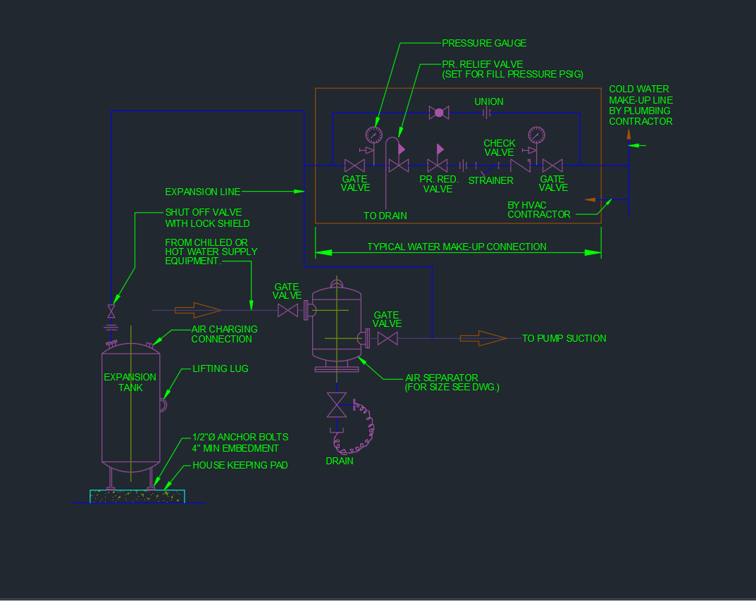
An Expansion Tank and Air Separator are essential components in a closed-loop HVAC water system. They help maintain system pressure, absorb thermal expansion, and remove entrapped air from the circulating water. This AutoCAD DWG drawing provides a detailed schematic of the piping arrangement between the expansion tank, air separator, and pump suction line, suitable for both chilled and hot water systems.
This file is ideal for MEP engineers, mechanical contractors, and HVAC system designers who need a precise and ready-to-use diagram for pressure maintenance systems.
Key Components in the Drawing
1. Expansion Tank
- Function: Absorbs the increase in water volume due to temperature rise in a closed hydronic system.
- Features:
- Air charging connection
- Shut-off valve with lock shield
- Lifting lug and anchoring base details
- Mounted on a housekeeping pad with ½” Ø anchor bolts (4” embedment)
- Connections:
- Connected to the system via expansion line from the chilled or hot water supply.
- Equipped with a gate valve for isolation and maintenance.
2. Air Separator
- Function: Removes entrained air bubbles from the circulating water to prevent cavitation and noise.
- Details Included:
- Drain valve for sediment removal
- Connection to the pump suction line
- Gate valve isolation on both inlet and outlet
- Design Note: Size selection per manufacturer’s data or system flow rate requirements.
3. Water Make-Up Assembly
Ensures automatic refilling of the HVAC loop when water loss occurs. Components include:
- Pressure Gauge – Monitors system fill pressure.
- Pressure Relief Valve (PRV): Factory set to system fill pressure (PSIG).
- Pressure Reducing Valve: Maintains fill pressure under dynamic conditions.
- Strainer: Protects valves from dirt or debris.
- Check Valve: Prevents backflow from the system.
- Union: Allows for easy maintenance.
- Drain Connection: For flushing and servicing.
This assembly is typically installed by the HVAC contractor, with connection to the cold water supply line provided by the plumbing contractor.
System Flow Overview
- Water from the chilled or hot water system flows through the expansion line into the expansion tank.
- The air separator, located near the pump suction line, continuously removes entrained air from the circulating water.
- Make-up water is introduced through the automatic fill assembly, maintaining system pressure.
- Excess air and pressure are released through the pressure relief valve and drain line.
Technical Details
| Component | Function / Description |
|---|---|
| Expansion Tank | Absorbs thermal expansion, maintains pressure stability |
| Air Separator | Removes entrapped air from circulating water |
| Pressure Reducing Valve | Automatically maintains set system pressure |
| Pressure Relief Valve | Protects system from overpressure |
| Strainer | Filters impurities from incoming make-up water |
| Gate Valves | Isolation during maintenance |
| Check Valve | Prevents reverse flow |
| Drain Connection | Allows periodic system flushing |
| Pressure Gauge | Monitors system fill pressure |
Installation Notes
- Expansion Tank Position:
- Install close to the suction side of the pump for accurate pressure control.
- Mount vertically on a reinforced concrete base.
- Air Separator Location:
- Place on the main line near the pump suction to remove air efficiently.
- Include isolation valves for maintenance.
- Piping Material:
- Use galvanized steel or copper pipes per system pressure rating.
- Apply PTFE sealing tape for threaded connections.
- Pressure Settings:
- Pre-charge expansion tank to system fill pressure before connection.
- Verify pressure reducing valve and relief valve settings as per design specifications.
- Maintenance Access:
- Provide clearance for removing strainers, gauges, and valves.
- Ensure accessible drain points for easy servicing.
Applications
The Expansion Tank and Air Separator DWG detail is used in:
- Chilled Water Systems for air conditioning plants.
- Hot Water Systems for heating circuits.
- Hydronic Loops in commercial and industrial HVAC installations.
- Closed-loop condenser water systems.
This layout ensures optimal system pressure stability, pump efficiency, and air removal performance.
Advantages of Using This DWG
✅ Standardized Detailing: Based on HVAC and ASHRAE design conventions.
✅ Ready-to-Use AutoCAD Block: Easy insertion into mechanical layouts.
✅ Layer-Organized Drawing: Clear identification of HVAC and plumbing scopes.
✅ Time-Saving Resource: Reduces drafting and design setup time.
✅ Professional Documentation: Ideal for tender drawings and shop submissions.
Conclusion
The Expansion Tank and Air Separator Piping Diagram DWG provides a complete schematic for closed-loop HVAC water systems. It illustrates all key valves, fittings, and safety devices needed for pressure control and air separation.
This AutoCAD drawing is an essential reference for mechanical and plumbing engineers, ensuring safe, efficient, and maintainable hydronic system operation.
⬇ Download AutoCAD File