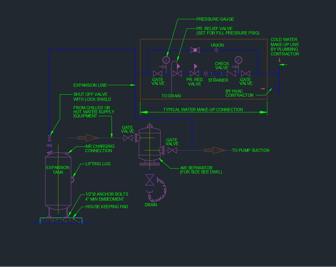
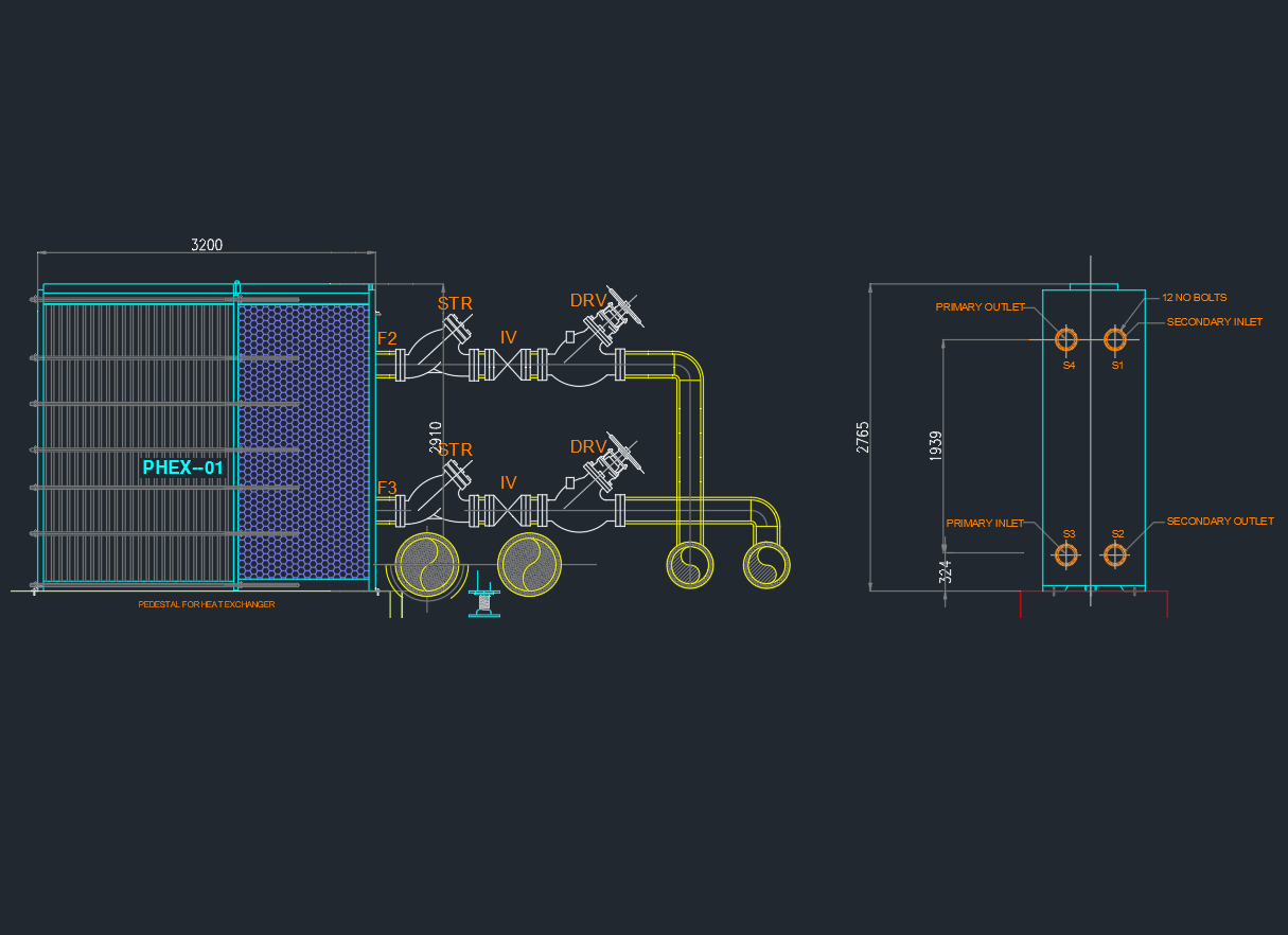
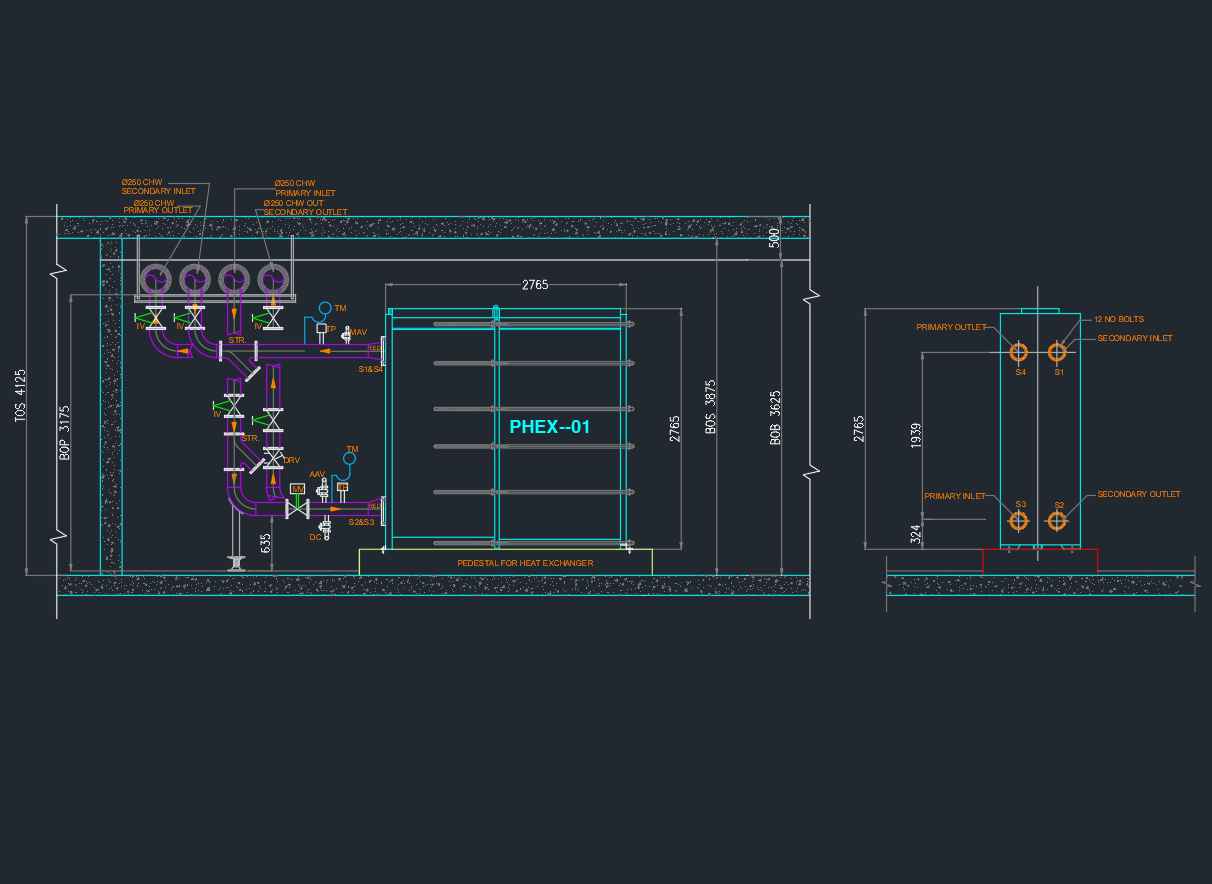
The Expansion Tank and Air Separator Piping Diagram AutoCAD Drawing provides a detailed schematic showing how these two essential HVAC components are connected within a closed-loop chilled or hot water system. This DWG file includes piping connections, valves, strainers, pressure gauges, and flow direction indicators — ensuring proper system operation, air removal, and pressure control. Perfect for HVAC engineers, MEP designers, and contractors, this drawing supports accurate layout design and equipment coordination. Download this expansion tank and air separator AutoCAD DWG to enhance your HVAC documentation, improve system reliability, and ensure code-compliant installation.
⬇ Download AutoCAD FileExpansion Tank and Air Separator Piping Diagram AutoCAD Drawing