Introduction
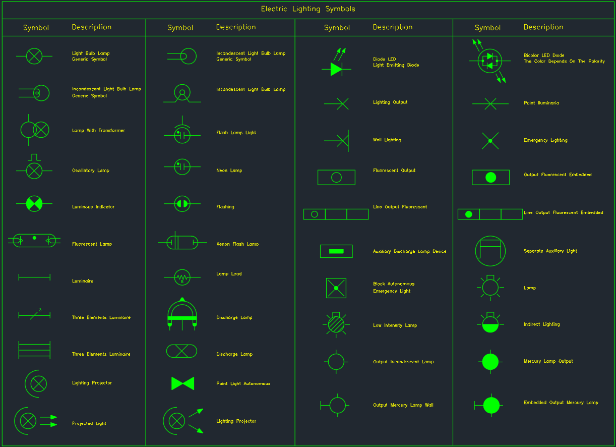
Electric Lighting Symbols are essential elements in electrical design drawings, used to represent various types of lighting fixtures and components in schematic and layout plans. These standardized symbols ensure clear communication between electrical engineers, architects, and construction teams during the design and installation of lighting systems.
This AutoCAD DWG set provides a comprehensive collection of lighting symbols, including lamps, luminaires, projectors, LEDs, and fluorescent fittings, suitable for residential, commercial, and industrial applications.
Importance of Electric Lighting Symbols in CAD Drawings
Lighting symbols form the foundation of every lighting layout plan and electrical schematic drawing. By using standardized CAD symbols, designers can:
- Ensure clarity and accuracy in electrical documentation.
- Simplify coordination among design disciplines (architectural, MEP, and interior).
- Maintain compliance with international drafting standards such as IEC, IEEE, and ANSI.
- Accelerate drawing production in AutoCAD and Revit workflows.
In short, well-defined lighting symbols help engineers and drafters produce professional and code-compliant electrical layouts.
Common Lighting Symbols Included in This DWG
1. Basic Lamp and Bulb Symbols
- Light Bulb Lamp Generic Symbol – Represents a standard light bulb or general illumination fixture.
- Incandescent Light Bulb – Used for traditional lighting systems and residential wiring diagrams.
- Luminous Indicator / Neon Lamp – Indicates control panel status or signal lights.
2. Fluorescent and LED Lighting
- Fluorescent Lamp Symbol – Denotes tube light fixtures in ceilings or walls.
- Line Output Fluorescent / Embedded Fluorescent – Represents linear lighting in false ceilings or architectural lighting strips.
- LED Diode Symbol – Used for modern energy-efficient lighting systems.
- Bicolor LED Diode – Indicates dual-color LEDs, often used in status indicators.
3. Emergency and Specialized Lights
- Emergency Lighting Symbol – Marks locations of safety or evacuation lights.
- Autonomous Emergency Light Block – Represents self-powered emergency luminaires.
- Auxiliary Discharge Lamp Device – Used for emergency and industrial high-intensity lighting.
4. Luminaires and Fixtures
- Luminaire / Three-Element Luminaire – Shows ceiling-mounted or wall-mounted fixtures.
- Lighting Projector / Projected Light – Used for stage, landscape, or accent lighting.
- Indirect Lighting Symbol – Represents lights reflecting off walls or ceilings for soft illumination.
5. Specialized Lamps
- Mercury Lamp Output / Embedded Output Mercury Lamp – Used in industrial or outdoor lighting applications.
- Discharge Lamp / Xenon Flash Lamp – For photography, laboratories, or technical environments.
- Low Intensity and High Intensity Lamps – Represent variations in light output for specific environments.
Applications in Electrical and MEP Drawings
The Electric Lighting Symbols DWG collection is widely applicable across:
- Architectural lighting layouts – For interior designers and building planners.
- Electrical circuit diagrams – For load distribution and power schematics.
- MEP coordination drawings – Ensuring clear visualization between HVAC, plumbing, and lighting systems.
- Industrial plant layouts – For factory, warehouse, or process area lighting.
Using standardized CAD symbols not only ensures professional presentation but also improves workflow efficiency and minimizes design conflicts.
How to Use the DWG Symbols
- Import into AutoCAD or Revit – Simply insert the DWG into your lighting layout template.
- Scale and Layer Management – Adjust symbol sizes and assign appropriate layers (e.g., “E-LIGHT”, “E-FIXTURE”).
- Annotate and Tag – Add lighting labels such as “L1”, “L2”, or fixture IDs for scheduling.
- Coordinate with Electrical Panel Layouts – Link symbols to circuits and load calculations for full system integration.
These steps help maintain a professional, code-compliant, and easily editable lighting plan.
Conclusion
The Electric Lighting Symbols DWG file is an indispensable tool for electrical engineers, CAD drafters, and lighting designers. It provides a complete visual language for representing lamps, fixtures, LEDs, and emergency lighting systems in AutoCAD drawings. By using these standardized symbols, you can enhance your project documentation, reduce drafting time, and ensure smooth project coordination.