Introduction
A Duct Support Typical Detail is a fundamental element in HVAC (Heating, Ventilation, and Air Conditioning) system design. It defines how air ducts are suspended from building structures, ensuring proper alignment, stability, and vibration control.
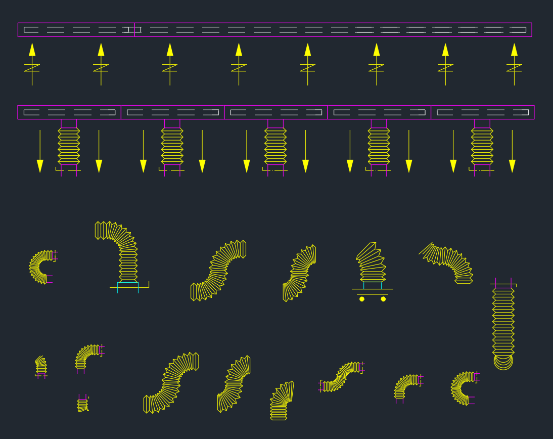
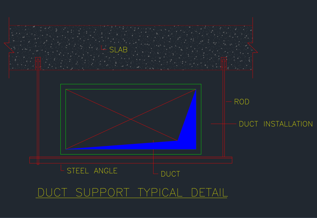
This drawing illustrates a standard hanging duct support system using rods and steel angles connected to the concrete slab. It provides engineers and designers with a reliable reference for air distribution system layouts.
Components of the Duct Support Detail
1. Slab
The slab serves as the structural base from which the duct support is suspended. Typically made of reinforced concrete, it provides the necessary strength to anchor the threaded rods that carry the duct’s weight.
2. Rod
The rod or hanger rod is used to connect the slab to the duct support frame. Made from galvanized steel, it ensures load-bearing capability and minimizes deflection under heavy duct sections. Proper rod spacing and sizing are essential to meet design codes such as SMACNA (Sheet Metal and Air Conditioning Contractors’ National Association) standards.
3. Steel Angle
The steel angle frame forms the base platform on which the duct rests. It provides rigidity, maintains duct alignment, and allows for easy adjustment during installation. Common sizes include L50×50×6 mm or L65×65×8 mm, depending on duct dimensions and weight.
4. Duct
The duct represents the main air passage—fabricated from galvanized sheet metal, aluminum, or stainless steel. In this typical detail, the duct sits on the steel angle, supported by rods on both sides. Cross bracing may be added for structural stability.
5. Duct Insulation
In HVAC systems, ducts are often insulated to prevent energy loss and condensation. The insulation layer surrounds the duct, maintaining air temperature and improving energy efficiency.
Importance of Duct Support Design
Proper duct support detailing is critical for ensuring system reliability and safety. Poorly designed or installed supports can lead to vibration, noise, and even structural failure. Key objectives of an effective duct support system include:
-
Load Distribution: Evenly transferring the weight of ducts and air pressure forces to the building structure.
-
Alignment Control: Maintaining level positioning and correct slope for air distribution.
-
Vibration Isolation: Reducing noise caused by fans, dampers, and air movement.
-
Thermal Protection: Supporting insulated ducts without compressing or damaging the insulation layer.
-
Ease of Maintenance: Allowing access for cleaning, inspection, or filter replacement.
Design Considerations for Duct Support
1. Support Spacing
Duct support spacing depends on duct material, size, and thickness. For rectangular galvanized ducts, spacing usually ranges from 2.0 to 3.0 meters. Heavier ducts or insulated ducts may require closer spacing.
2. Rod Diameter and Anchor Type
Select the rod diameter based on the total load, including duct weight, air pressure, and accessories. Common diameters range from M8 to M12. Anchors should be expansion bolts or chemical anchors rated for overhead applications.
3. Cross Bracing and Stability
For large ducts, cross bracing is often added between rods to prevent lateral movement. This ensures the support frame remains stable under dynamic loads.
4. Material Coating
To prevent corrosion, especially in humid or outdoor environments, use hot-dip galvanized or epoxy-coated components.
5. Fire and Seismic Safety
In fire-rated or seismic zones, duct supports must comply with local building codes. Fire collars, flexible joints, and seismic restraints may be added for safety.
Application Areas
The Duct Support Typical Detail applies to various HVAC and mechanical systems, including:
-
Air supply and return ducts in commercial buildings
-
Exhaust systems in industrial plants and kitchens
-
Chilled air distribution in large HVAC networks
-
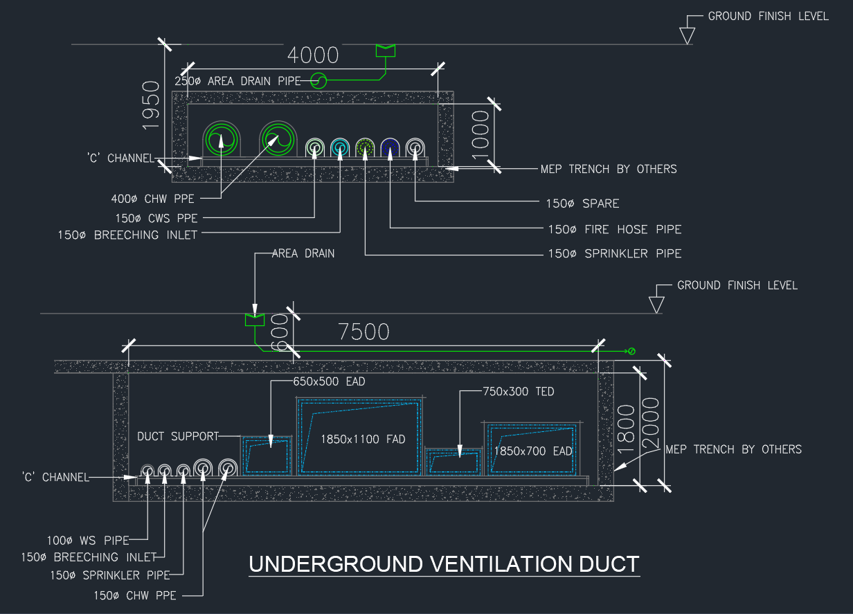
Ventilation ducts in basements and underground facilities
This DWG detail provides a standardized and code-compliant reference that simplifies coordination among architects, structural, and MEP engineers.
Conclusion
The Duct Support Typical Detail is an indispensable drawing in HVAC design and documentation. It ensures ducts are properly suspended, aligned, and supported, maintaining system performance and safety throughout the building’s life. By using standard AutoCAD DWG details, engineers can streamline design coordination and reduce construction errors.
⬇ Download AutoCAD File