Introduction
A reliable chilled water network depends on more than pumps and chillers. Every valve, elbow, tee and reducer affects hydraulic performance, pressure drop and maintenance access. That is why a clear, well-organized chilled water pipe fittings and valves library is essential for professional HVAC drawings.
This DWG set collects all major valve and fitting types used on chilled water mains and branches, organized by nominal bore. It is designed for MEP engineers, CAD designers and contractors who want consistent, readable plans that coordinate easily with architectural and structural layouts.
Overview of the DWG Library
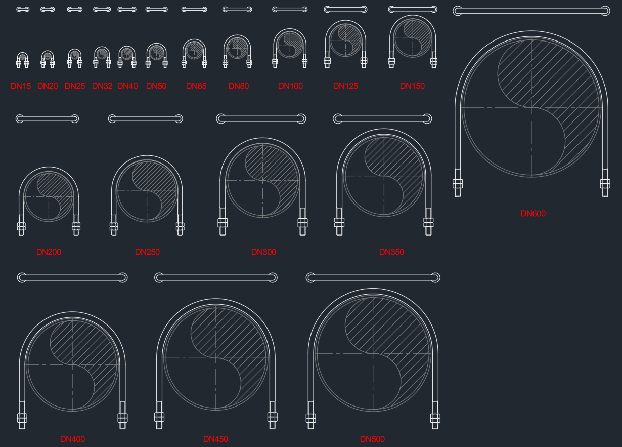
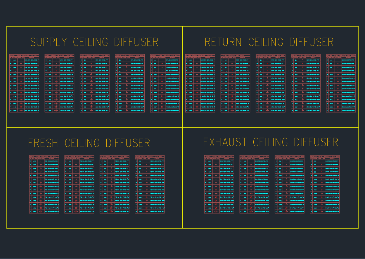
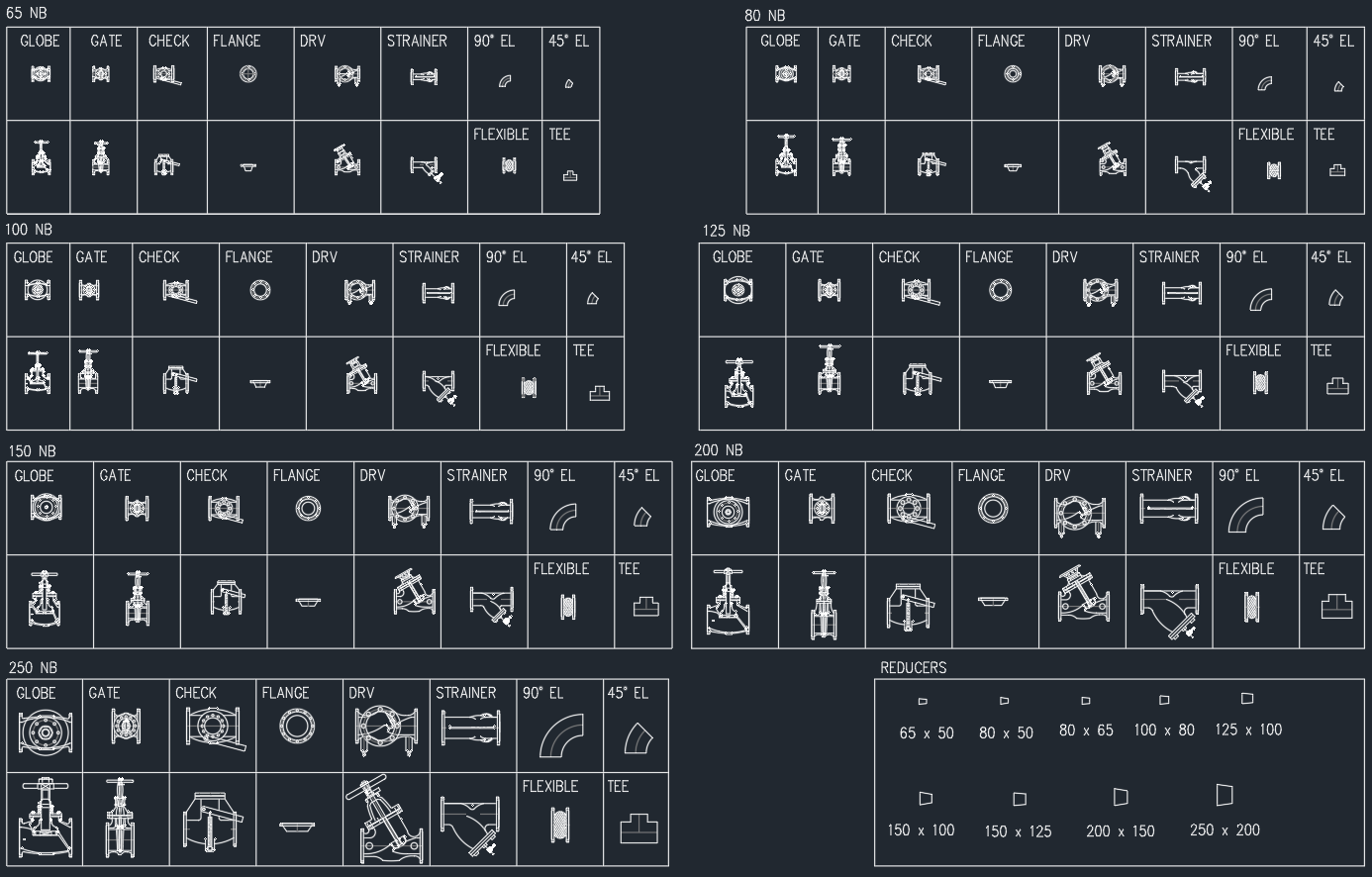
The chilled water pipe fittings and valves drawing is arranged by pipe size: 65 NB, 80 NB, 100 NB, 125 NB, 150 NB, 200 NB and 250 NB. For each size, the library includes globe valves, gate valves, check valves, flanges, double regulating valves (DRV), strainers, 90° elbows, 45° elbows, flexible connectors and tees. A dedicated reducer panel lists all common size transitions.
Grouping symbols by nominal bore helps designers pick the right block faster and keeps the drawing visually consistent. You can copy the required fitting or valve directly into pump sets, risers, plant rooms and horizontal distribution runs.
Valve Types in the Chilled Water System
Globe and gate valves
Globe valves provide fine control and throttling. They appear in the library as detailed front and side views, scaled for each pipe size. Gate valves are used mainly for isolation, offering full-bore flow with minimal pressure loss. Having both valves defined in the chilled water pipe fittings and valves legend allows you to show clearly which locations are for control and which are for shut-off.
Check valves
Check valves protect pumps and chillers from reverse flow and water hammer. The DWG includes swing or lift-type check valve blocks for all diameters, showing the correct flow direction. When placed on schematics and plan views, these symbols make system flow paths easy to understand for commissioning teams and maintenance staff.
Double regulating valves (DRV)
Balancing is critical in large chilled water systems. The DRV symbols in the chilled water pipe fittings and valves set mark key points where differential pressure and flow can be adjusted. Consistent DRV representation supports accurate valve schedules, TAB reports and future rebalancing work.
Fittings for Accurate Coordination
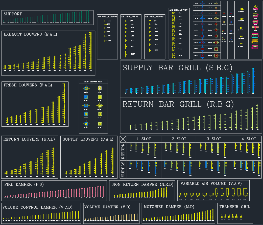
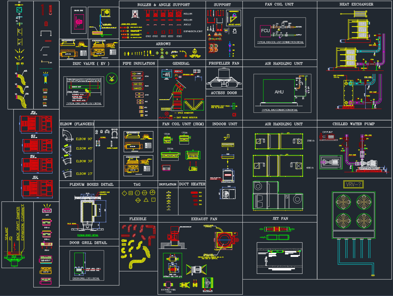
Strainers and flanges
Y-type strainers protect downstream equipment from debris. Their orientation and access for cleaning are shown clearly in each block. Flange symbols indicate demountable joints, which are vital around pumps, control valves and heat exchangers. With these fittings standardized, your chilled water pipework layout becomes much easier to read and build.
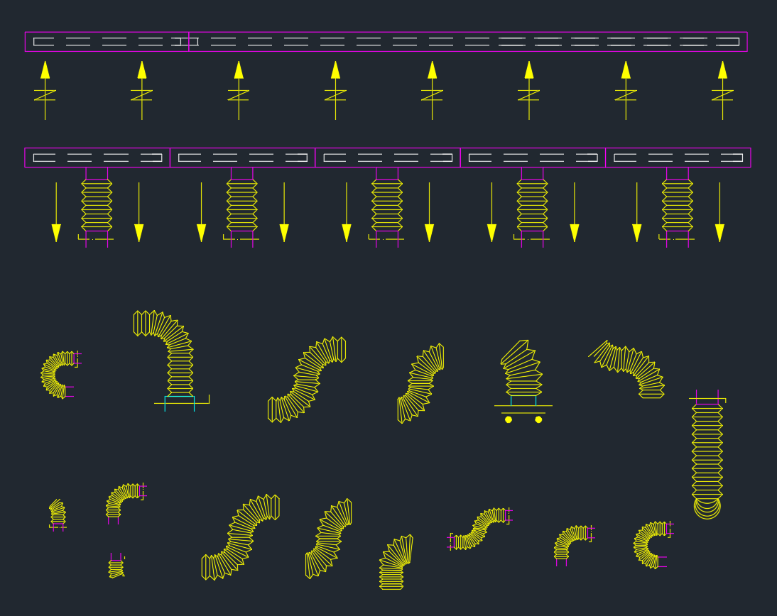
Elbows, tees and flexible connectors
The library contains 90° elbows, 45° elbows and tees for each nominal bore. These fittings are used to model direction changes, branch connections and manifold layouts. Flexible connectors are also provided to indicate vibration isolation at pumps, chillers and AHUs. Using these standard blocks ensures that offsets, clearances and support locations are consistent from drawing to drawing.
Reducers
Reducers are shown in a separate panel with common transitions such as 65×50, 80×65, 100×80, 125×100, 150×100, 150×125, 200×150 and 250×200. Including reducers in the chilled water pipe fittings and valves legend helps designers manage velocity changes and maintain proper flow regimes when pipe sizes step up or down.
Benefits of a Standard CHW Fittings and Valves Legend
Adopting this chilled water pipe fittings and valves DWG library offers several practical advantages:
-
Consistent documentation – every project uses the same symbols, reducing confusion for installers and inspectors.
-
Faster drafting – engineers and CAD technicians copy ready-made blocks instead of drawing fittings from scratch.
-
Better coordination – accurate symbol sizes and clear geometry make clash detection and 3D coordination more reliable.
-
Easier scheduling – valve and fitting counts are easier to extract when the symbols are standardized across all drawings.
How to Use This DWG Library in AutoCAD
To get the most value from the chilled water pipe fittings and valves set, insert the DWG into your template or standards file. Create dedicated layers for CHW supply, CHW return and accessories. When drafting, select the block that matches the pipe size and rotate it to follow the line direction.
Use consistent annotation for valve tags, flow arrows and reference notes. If your office works in BIM as well as CAD, you can also use this 2D library as the plan symbol standard while linking each item to a 3D family in your model.
Conclusion
A complete chilled water pipe fittings and valves library is a powerful asset for any HVAC design team. By standardizing valves, elbows, tees, strainers, flexible connectors and reducers across all pipe sizes, this DWG set improves drawing quality, speeds up production and supports accurate installation on site. Add it to your CAD standards today to upgrade the clarity and professionalism of your chilled water piping layouts.
⬇ Download AutoCAD File