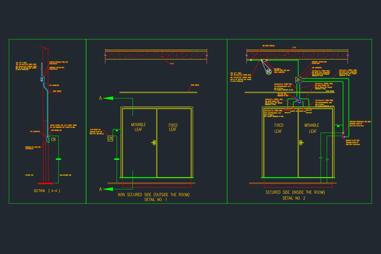
The Door Key Access Typical Detail drawing illustrates how a mechanical key access system is integrated into doors for controlled entry.
This AutoCAD DWG file includes lockset assembly, key cylinder installation, and door hardware configuration — suitable for architectural, security, and facility management drawings.
It’s ideal for architects, interior designers, and building engineers working on access control or door schedule detailing.
What Is a Door Key Access Detail?
A door key access detail defines the mechanical layout and installation method of a keyed lock system.
It shows how door leaf, frame, and lock components are coordinated to ensure smooth operation, security, and long service life.
Common use cases include:
- Office and residential door access systems
- Utility room and service door security
- Mixed-use building door hardware schedules
- Hotel, hospital, and institutional facility layouts
Main Components in the Drawing
| No. | Component | Description |
|---|---|---|
| 1 | Door Leaf | The main door panel or slab |
| 2 | Lockset / Key Cylinder | Provides mechanical locking mechanism |
| 3 | Handle / Lever Set | Enables manual operation of latch |
| 4 | Strike Plate | Fixed to frame to receive latch bolt |
| 5 | Door Frame / Jamb | Supports hinges and latch alignment |
| 6 | Key Access Marking (TYP.) | Indicates typical keyed access door |
| 7 | Label or Schedule Tag | Refers to door hardware schedule (DHS) |
AutoCAD DWG Download
The DWG file includes:
- Door and frame section details
- Key lockset and latch mechanism layout
- Typical elevation and plan view
- Hardware annotation and layer separation
[Download Door Key Access Typical Detail DWG]
(AutoCAD 2018 format – suitable for architectural, interior, and security design documentation.)
Installation Guidelines
- Ensure lockset height consistency (usually 1000–1050 mm from floor).
- Align key cylinder center with handle axis.
- Confirm frame reinforcement for heavy-duty doors.
- Specify door handing (left or right hinge).
- Include access control tag or identifier if required by security plan.
- Test alignment before final fixing.
Applicable Standards
- BS EN 12209 – Mechanically Operated Locks and Latches
- ANSI/BHMA A156.13 – Mortise Locks and Latches
- ISO 18101 – Door Hardware Mounting Guidelines
- Architectural Door Schedule Standards (AIA/CSI)
Advantages
✅ Ensures consistent lockset installation across all doors
✅ Improves building security and access management
✅ Compatible with various lockset brands and keying systems
✅ Suitable for AutoCAD-based door schedule drawings
✅ Saves drafting time with editable CAD layers
Conclusion
The Door Key Access Typical Detail is a fundamental drawing for any architectural or security system design.
Download the AutoCAD DWG file and use it in your project door schedule, construction documents, or key plan layout.