Introduction
Accurate electrical documentation depends on clear, consistent symbols. When designing low-voltage and medium-voltage systems, a complete set of distribution panel symbols helps engineers, CAD designers and contractors understand how power flows through switchboards and panel boards. Using a standard DWG legend for breakers, meters, transformers and control devices saves time, reduces errors and keeps drawings compliant with project specifications.
What Are Distribution Panel Symbols?
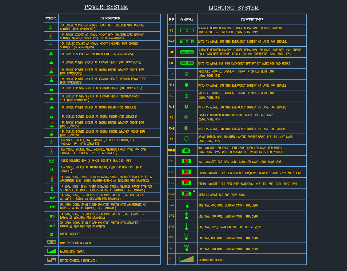
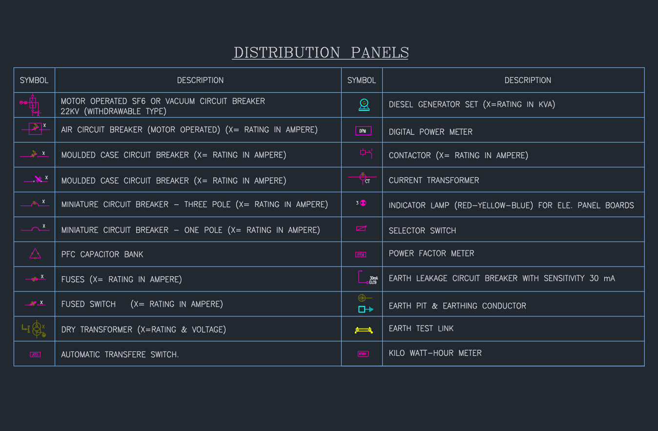
Distribution panel symbols are graphical icons used on single line diagrams and panel schedules to represent equipment inside an electrical distribution board. Typical items include circuit breakers, fused switches, capacitor banks, current transformers, diesel generator connections, power meters and automatic transfer switches.
By placing all distribution panel symbols together in one legend block, every stakeholder can read the drawing with the same interpretation. The legend explains exactly how each symbol is used, what rating is required and how the device fits into the overall protection and metering scheme.
Key Symbols in a Distribution Panel Legend
Circuit breakers and protection devices
The core of any panel legend is the family of circuit breaker symbols. These commonly cover:
-
Motor operated SF6 or vacuum circuit breakers for medium-voltage feeders
-
Air circuit breakers for main low-voltage incomers
-
Moulded case circuit breakers with configurable ampere ratings
-
Miniature circuit breakers in single-pole and three-pole versions
-
Fuses and fused switches for smaller branch circuits
These distribution panel symbols allow the designer to show where protection is provided, how loads are grouped and which breakers are suitable for isolation or motor starting.
Reactive power and power quality equipment
Many distribution panel legends also include a PFC capacitor bank symbol to indicate power factor correction. When combined with a power factor meter, designers can model how reactive compensation improves system efficiency and reduces penalties from the utility. Clear symbols support good coordination between the electrical consultant, panel builder and commissioning team.
Metering and monitoring instruments
Precise metering is essential for energy management. Typical distribution panel symbols for metering include:
-
Digital power meter
-
Kilowatt-hour meter
-
Current transformer
-
Power factor meter
-
Indicator lamps for phase presence on panel doors
Using dedicated symbols for each metering device keeps single line diagrams easy to read while providing enough detail for accurate wiring diagrams later.
Control and changeover devices
A professional legend also covers control items such as selector switches, earth leakage circuit breakers, earth test links and earth pits. For backup power, the distribution panel symbol set normally includes a diesel generator connection and an automatic transfer switch. These icons show how the normal and emergency sources are switched, ensuring continuity of supply to critical loads.
Benefits of Using a Standard DWG Legend
Having a single DWG file that contains all distribution panel symbols delivers several practical benefits:
-
Consistency across projects – teams in different offices or on different jobs use the same graphical language.
-
Faster drafting – CAD users simply insert the legend and copy symbols instead of redrawing devices.
-
Reduced site queries – installers can quickly identify breakers, meters and earthing components, lowering the risk of misinterpretation.
-
Easier updates – when a standard changes, the master legend is revised once and reused everywhere.
For companies that manage many panel designs, a standard legend is an important part of their CAD standards library.
How to Use Distribution Panel Symbols in AutoCAD
To use these distribution panel symbols effectively, insert the legend DWG on your general notes or single line diagram sheet at a clear scale. Lock the legend on a dedicated layer so it cannot be moved accidentally. When you create new panels, copy the required symbols from the legend and place them on the diagram with correct tag numbers, breaker ratings and feeder names.
Avoid inventing new icons in the middle of a project. If a new device type is required, add it properly to the legend with a short but precise description. This keeps the distribution panel symbols synchronized with your internal standards and with external panel manufacturers.
Conclusion
Distribution panel symbols may look simple, but they are vital for communicating how electrical power is protected, measured and controlled in a building. A well-structured DWG legend for breakers, meters, transformers, earthing equipment and transfer switches improves clarity for engineers, architects, contractors and inspectors. By using standard distribution panel symbols on every project, you create professional documentation that is easier to build, test and maintain over the life of the installation.
⬇ Download AutoCAD File