Introduction
A diaphragm pump is a type of positive displacement pump that uses a flexible diaphragm and check valves to move fluids.
It is widely used for chemical transfer, wastewater treatment, and process applications where leakage-free operation is critical.
In this article, you’ll learn how a diaphragm pump works, key parts, P&ID symbols, and can download a ready-to-use AutoCAD DWG block for your design projects.
1. What Is a Diaphragm Pump?
A diaphragm pump moves liquid using a reciprocating diaphragm made from rubber, Teflon, or other flexible material.
The diaphragm alternately expands and contracts, creating suction and discharge cycles — allowing fluid to flow in one direction through inlet and outlet check valves.
💡 No mechanical seals are needed, making diaphragm pumps ideal for abrasive, viscous, or corrosive fluids.
2. Working Principle
Step 1: Suction Stroke
-
The diaphragm moves backward.
-
Pressure in the pump chamber drops.
-
Inlet check valve opens, drawing liquid in.
-
Outlet valve closes to prevent backflow.
Step 2: Discharge Stroke
-
The diaphragm moves forward.
-
Pressure increases inside the chamber.
-
Outlet check valve opens, discharging fluid.
-
Inlet valve closes to stop return flow.
Repeat this motion continuously for constant pumping action.
3. Types of Diaphragm Pumps
| Type | Drive Mechanism | Typical Use |
|---|---|---|
| Air-Operated Double Diaphragm (AODD) | Compressed air | Chemical transfer, portable pumps |
| Hydraulically Operated | Hydraulic fluid moves diaphragm | Industrial process, high pressure |
| Mechanically Driven | Cam or crankshaft actuated | Metering and dosing systems |
🧩 The AODD pump is the most common — self-priming, explosion-proof, and capable of dry running.
4. Major Components
| Component | Function |
|---|---|
| Flexible Diaphragm | Separates fluid and air chambers; provides suction and discharge motion |
| Air Valve / Drive Section | Alternates air pressure between diaphragms (AODD type) |
| Inlet & Outlet Check Valves | Ensure one-way flow |
| Manifold & Casing | Channels the fluid |
| Bolts, Seats, and O-Rings | Maintain leak-tight assembly |
5. Advantages
✅ Handles viscous, abrasive, and corrosive fluids
✅ Self-priming and dry-running capability
✅ Portable and explosion-safe (AODD)
✅ No shaft seals → zero leakage
✅ Simple maintenance and compact design
6. Common Applications
-
Chemical and paint transfer
-
Food & beverage production
-
Wastewater treatment plants
-
Oil and gas refineries
-
Pharmaceutical processing
-
Tanker loading and unloading
7. P&ID Symbol for Diaphragm Pump
On a Piping & Instrumentation Diagram (P&ID), diaphragm pumps are represented by a circle with a flexible membrane symbol inside.
Typical tag examples:
-
P-101 A/B – Air-Operated Diaphragm Pump
-
P-302 – Metering Diaphragm Pump
The air supply and discharge lines are often annotated in P&IDs to show control logic and pulsation dampers.
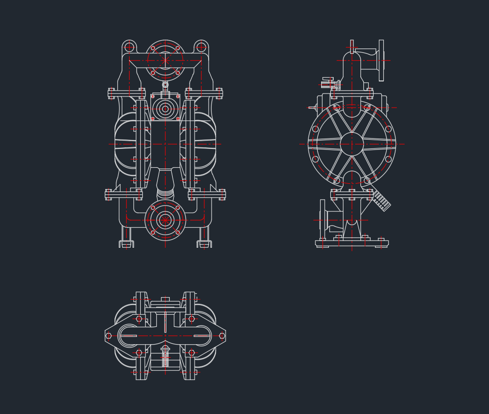
8. AutoCAD DWG Drawing Details
| Feature | Description |
|---|---|
| File Format | .DWG (AutoCAD 2007 or later) |
| Views | Plan, Front Elevation |
| Scale | 1:1 (true size) |
| Layers | Equipment, Centerline, Text |
| Category | Mechanical Equipment / Pumps |
License: Free for personal and educational use
9. Design & Installation Tips
-
Use pulsation dampeners to reduce vibration.
-
Keep suction lines short to improve efficiency.
-
Include pressure gauges and relief valves for safety.
-
Mount on anti-vibration pads for portable or skid setups.
-
Always check compatibility of diaphragm material with pumped fluid.
10. Conclusion
The Diaphragm Pump is a reliable and versatile pumping solution for handling difficult fluids.
Its leak-free design, self-priming capability, and adaptability make it an essential part of industrial, wastewater, and chemical plants.