A Dosing Pot is a crucial component in chilled water and closed-loop systems, used to introduce corrosion inhibitors, biocides, or other chemicals into the circulating water.
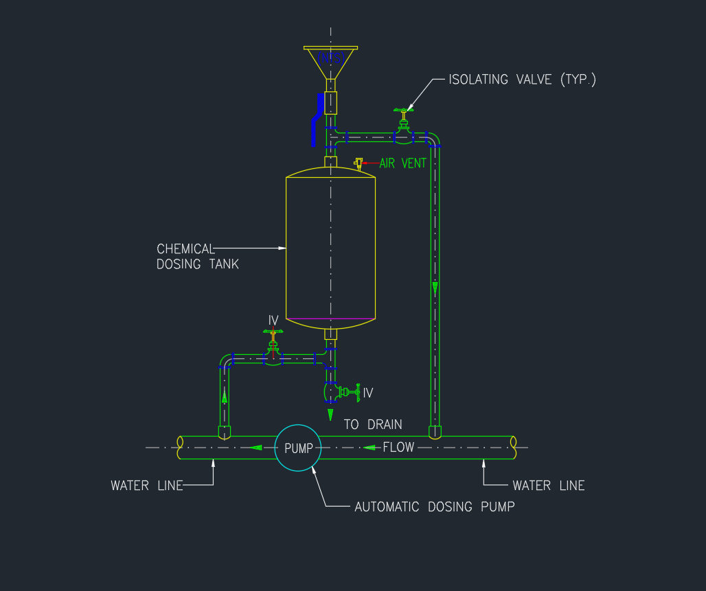
This AutoCAD drawing shows a typical Dosing Pot Connection Detail, including valves, dosing tank, pump arrangement, and pipe connections for proper chemical dosing operation.
Ideal for HVAC engineers, mechanical designers, and MEP contractors, this drawing ensures correct installation and maintenance access.
What Is a Dosing Pot?
A chemical dosing pot allows safe injection of treatment chemicals into closed water systems.
The pot is installed across the main water line — between the flow and return — so that chemicals can be introduced without interrupting operation.
Typical locations:
- Chilled Water Systems
- Condenser Water Systems
- Heating Water Loops
Main Components of the Dosing Pot Assembly
| No. | Component | Description |
|---|---|---|
| 1 | Chemical Dosing Tank | Receives the treatment chemical before injection |
| 2 | Isolating Valve (TYP.) | Allows isolation from main water line for maintenance |
| 3 | Automatic Dosing Pump | Pumps chemicals into the main system line |
| 4 | IV (Isolation Valve) | Controls inlet/outlet during filling and draining |
| 5 | Air Vent | Releases trapped air during filling |
| 6 | Drain Valve | Used to flush or empty the dosing pot |
| 7 | Water Line (Flow & Return) | Connection points to main chilled water circuit |
AutoCAD DWG Download
The DWG file includes:
- Typical schematic for dosing pot connection
- Flow and return line connection detail
- Isolation and drain valve arrangement
- Air vent and chemical dosing pump layout
- Layered and editable DWG for easy modification
Installation Guidelines
- Install the dosing pot between flow and return lines.
- Provide isolation valves on both sides.
- Fit an air vent at the top of the pot.
- Connect a drain valve at the bottom for cleaning.
- Use flexible connections for easy maintenance.
- Always follow system flow direction as shown in the schematic.
Applicable Standards
- ASHRAE 90.1 / 62.1 – HVAC System Design
- BS 8552:2012 – Water Treatment Systems
- CIBSE Commissioning Code W – Water Distribution Systems
Benefits
✅ Ensures clean and corrosion-free water systems
✅ Simple and safe chemical injection method
✅ Reduces downtime during maintenance
✅ Prolongs chiller and pump lifespan
Conclusion
The Detail of Dosing Pot Connections is a standard schematic for any HVAC chilled water system requiring water treatment.
Download the AutoCAD DWG to use in your project drawings, technical submissions, or MEP design documentation.