Introduction
A Concrete Pedestal is a reinforced concrete structural element designed to support steel columns, machinery bases, or heavy loads above the foundation level. It transfers vertical and horizontal loads safely into the footing while providing elevation and protection from surface moisture or soil exposure.
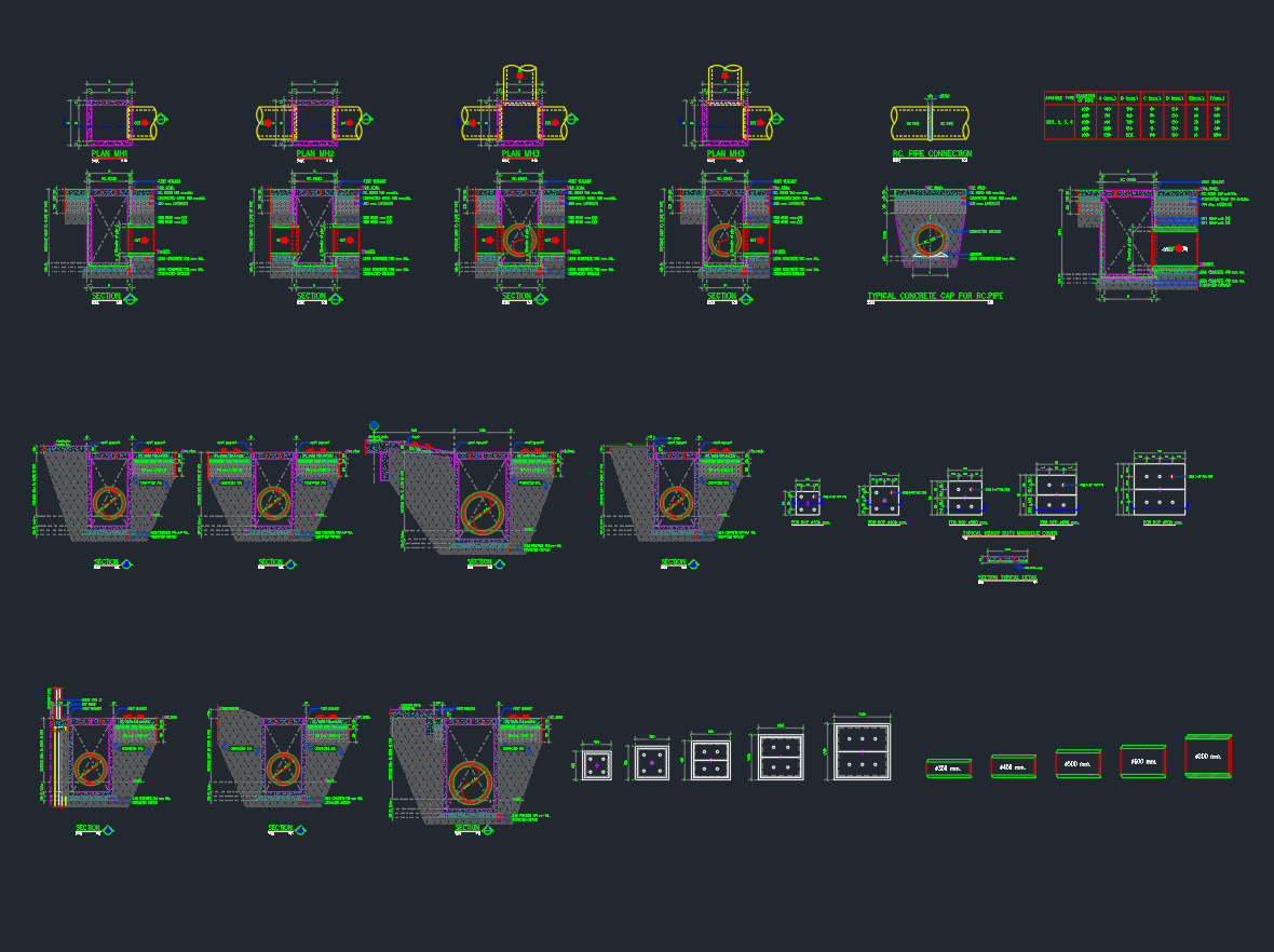
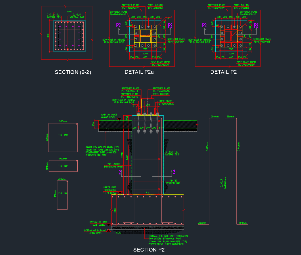
This AutoCAD DWG drawing provides a comprehensive section and detail view of a reinforced concrete pedestal (P2 type), including reinforcement bars, stiffener plates, and base plate configurations. It is suitable for structural engineers, civil designers, and construction professionals involved in industrial and commercial building design.
Components of the Concrete Pedestal Drawing
1. Section P2 – Vertical Section
The main section shows the complete pedestal assembly from the base plate to the foundation raft, including:
-
Steel Column: Centrally located, supported by a stiffened base plate.
-
Stiffener Plates: Welded to the column for lateral rigidity.
-
Base Plate (PL-700×700×50 mm): Transfers loads from the steel column into the concrete.
-
Anchor Bolts (M30×P4.5): Embedded in the pedestal for column connection stability.
-
Vertical Reinforcement Bars (T12–150): Provide structural strength against axial compression and bending.
-
Lateral Ties (T12–150): Constrain vertical bars to prevent buckling.
-
Foundation Interface: Pedestal embedded into a 1000 mm thick RC raft foundation.
2. Detail P2 and P2a – Top and Plan Reinforcement Layouts
These detail drawings illustrate the top view of the pedestal showing the placement of rebar, stiffener plates, and anchor bolts.
-
Stiffener Plates: 16 mm thick plates arranged around the column perimeter.
-
Base Plate Bolt Layout: Four to eight bolt holes positioned symmetrically.
-
Rebar Arrangement: Longitudinal and lateral steel layout maintaining clear cover distances.
-
Concrete Cover: Typically 50 mm minimum as per structural standards.
3. Section (2-2) – Cross-Sectional Reinforcement
This section highlights the reinforcement cage within the pedestal, including the spacing and configuration of vertical and horizontal steel bars for optimal strength and crack control.
Material and Design Specifications
| Item | Specification |
|---|---|
| Concrete Grade | C40/50 (or as per design) |
| Reinforcement Steel | T12 and T25 deformed bars (fy = 500 MPa) |
| Base Plate Material | Structural Steel (Grade 275 or 355) |
| Stiffener Plate | PL 12 mm / 16 mm thick |
| Anchor Bolts | M30 high-tensile headed stud anchor bolts |
| Foundation | 1000 mm RC raft with double reinforcement layers |
| Protective Coating | Two layers of bituminous paint at base and sides |
| Waterproof Layer | 200 µm polyethylene sheet under raft foundation |
Function and Purpose
The Concrete Pedestal serves several important structural functions:
-
Load Transfer: Safely transfers loads from steel columns or machinery into the foundation.
-
Elevation Control: Raises base plates above ground to protect against water and corrosion.
-
Vibration Isolation: Reduces transmission of vibrations from equipment to the foundation.
-
Durability: Extends service life of structural components by preventing moisture ingress.
Construction and Installation Notes
-
Ensure the anchor bolt template is accurately positioned before casting concrete.
-
Maintain a minimum clear cover of 50 mm around all reinforcement.
-
Apply bituminous paint on all pedestal surfaces below ground level for waterproofing.
-
Verify column alignment and bolt orientation before tightening.
-
Concrete should be vibrated and compacted properly to eliminate voids.
-
Allow full curing period before loading or column erection.
Applications
Concrete pedestals are widely used in:
-
Industrial Structures – Supporting steel columns, machinery, and heavy frames
-
Commercial Buildings – Transfer loads from ground-floor columns
-
Equipment Foundations – Pumps, generators, compressors
-
Bridges and Towers – Bearing supports for vertical loads
-
Storage Tanks and Pipelines – Elevated base supports
This DWG detail is suitable for inclusion in structural general arrangement drawings (GADs) and foundation detailing sheets.
Conclusion
The Concrete Pedestal DWG Detail offers a complete and precise drawing for engineers and designers involved in structural foundation design. It includes all necessary views—section, plan, and reinforcement details—ensuring compliance with construction standards and site practicality.
Use this DWG as a reliable reference for designing safe, durable, and efficient column support systems.
⬇ Download AutoCAD File