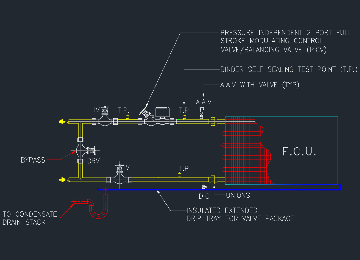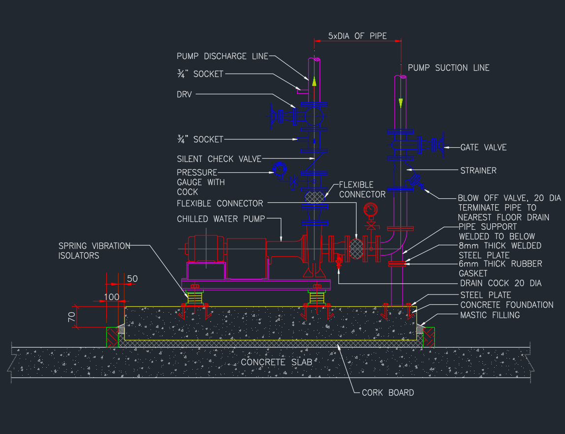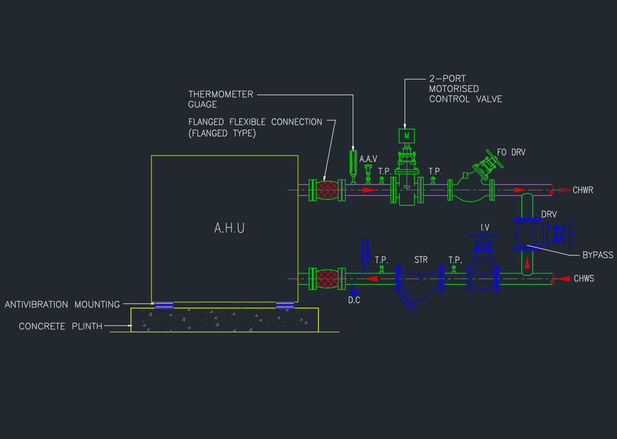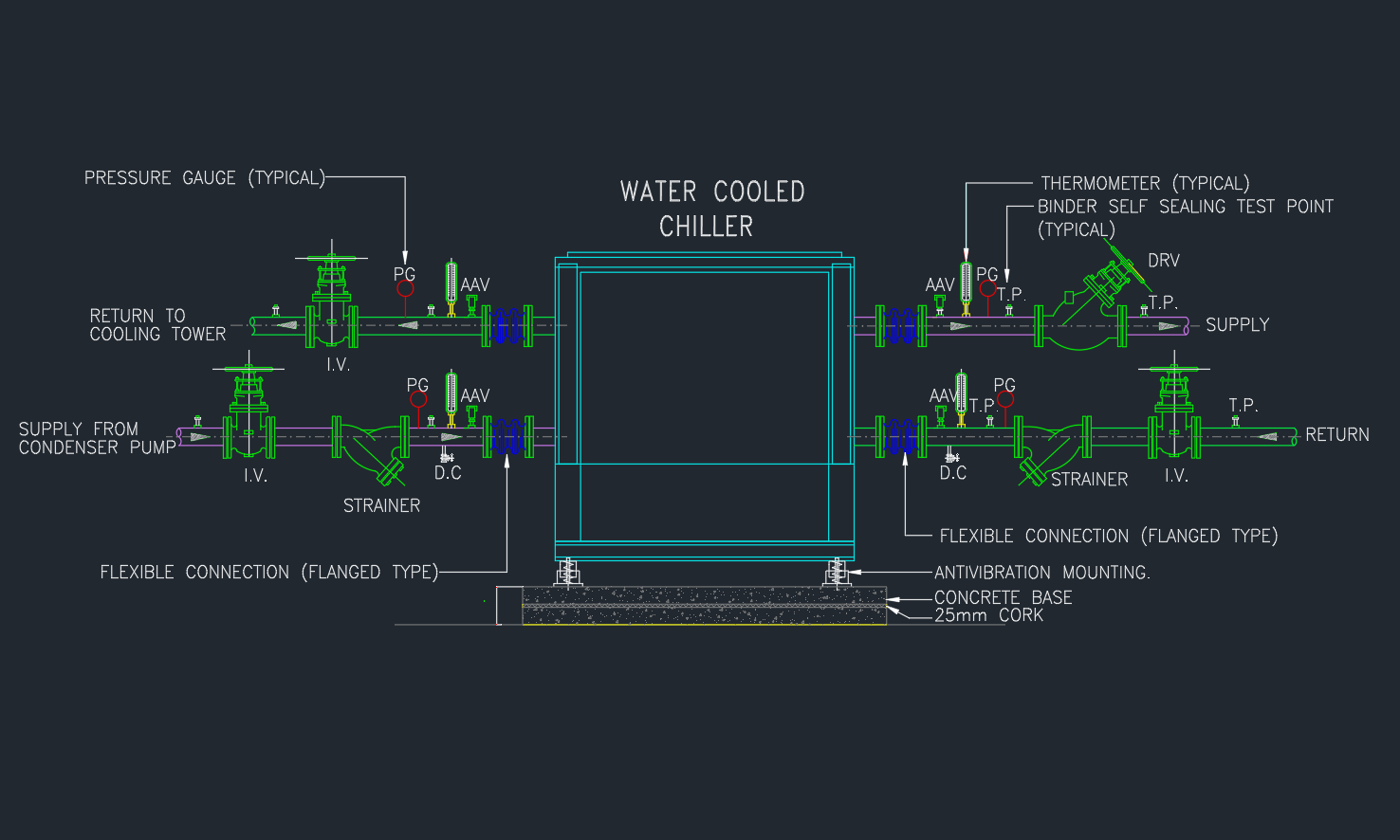
A Chiller Piping Connection Detail shows how chilled and condenser water lines are connected to the chiller unit in HVAC systems.
Proper piping arrangement is essential to ensure stable operation, smooth water flow, and maintenance access for mechanical systems.
This post provides a free AutoCAD DWG drawing showing the typical chiller piping connection detail, ideal for HVAC and MEP engineers.
What Is a Chiller Piping Connection?
A chiller is used to remove heat from a building by circulating chilled water through AHUs and FCUs.
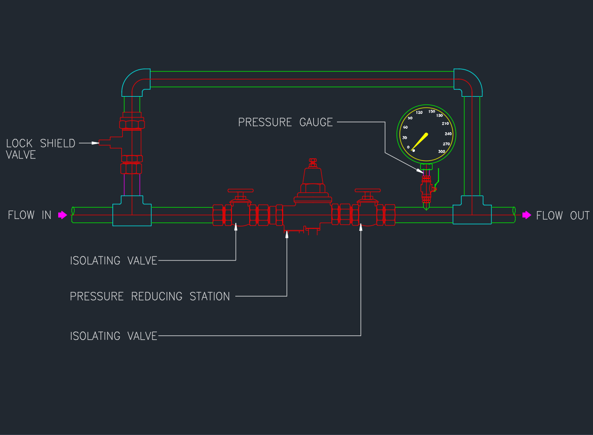
The piping connection ensures efficient transfer of chilled and condenser water between the chiller, pumps, and cooling tower.
It includes supply and return headers, valves, strainers, flexible joints, and instruments for pressure and temperature monitoring.
Main Components of a Chiller Connection
| No. | Component | Description |
|---|---|---|
| 1 | Isolation Valves | Allow maintenance without system shutdown |
| 2 | Y-Strainer | Filters debris before entering chiller |
| 3 | Flexible Connector | Reduces vibration from pump or equipment |
| 4 | Check Valve | Prevents reverse water flow |
| 5 | Temperature & Pressure Gauge | Monitors operating condition |
| 6 | Air Vent Valve | Releases trapped air in the pipeline |
| 7 | Drain Valve | For system cleaning and maintenance |
| 8 | Flow Meter / Balancing Valve | Controls and measures chilled water flow |
| 9 | Flanged or Grooved Connection | For easy installation and removal |
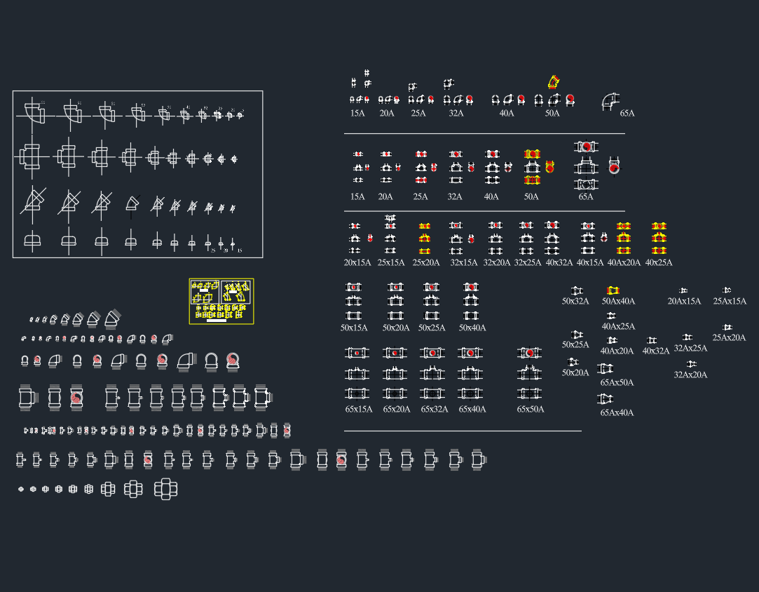
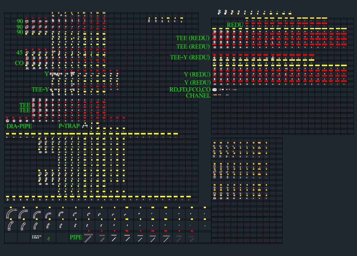
AutoCAD DWG Download
The drawing includes:
- Chiller water supply and return piping layout
- Flexible connection detail
- Valve and strainer arrangement
- Temperature/pressure gauge locations
- Typical mechanical room piping setup
Installation Guidelines
- Maintain proper flow direction (as indicated by chiller manufacturer).
- Install Y-strainer and isolation valve on chiller inlet.
- Use flexible connectors on both inlet and outlet lines.
- Provide pressure and temperature gauges near the chiller nozzles.
- Allow space for maintenance and tube pulling clearance.
- Use insulation on chilled water lines to prevent condensation.
Applicable Standards
- ASHRAE 90.1 / 62.1 – HVAC Design & Energy Efficiency
- SMACNA – HVAC Piping and Equipment Installation
- ASME B31.9 – Building Services Piping
- BS EN 12599 – Testing and Balancing HVAC Systems
Advantages of Proper Chiller Piping Design
✅ Increases chiller performance and reliability
✅ Reduces vibration and water hammer
✅ Prevents pressure drops and flow imbalance
✅ Simplifies maintenance and isolation
✅ Extends equipment service life
Conclusion
The Typical Chiller Piping Connection Detail is vital for the reliable operation of any HVAC chilled water system.
Download the AutoCAD DWG file and use it as a reference for your mechanical design, construction drawings, or MEP coordination.