Introduction
A precise Chilled Water Pump Valve Assembly detail is essential for reliable HVAC design. This AutoCAD DWG block provides coordinated plan, side view and elevation of a complete pump set, including isolation valves, non-return valves, strainers and associated pipework. With a ready-to-use assembly, MEP engineers and CAD designers can standardize pump station layouts, reduce drafting time and ensure clear construction documents for contractors and commissioning teams.
What Is a Chilled Water Pump Valve Assembly?
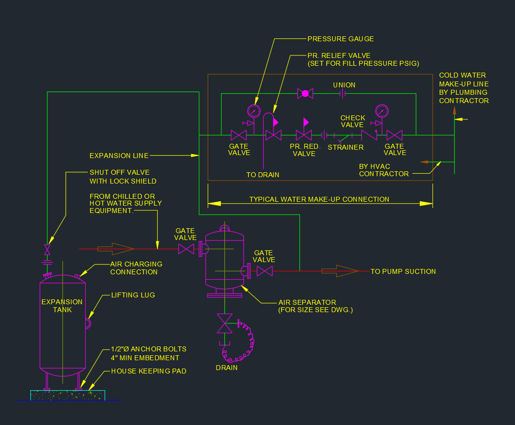
A Chilled Water Pump Valve Assembly is the combination of the pump, suction and discharge piping, isolation valves, check valves, drain points and measurement fittings installed on a chilled water line. It is usually located in the chiller plant room or mechanical floor and connects directly to the primary or secondary chilled water headers.
The assembly must allow safe isolation for maintenance, prevent reverse flow, provide throttling and balancing, and maintain correct system pressure. A clear CAD detail ensures that every component is properly coordinated with structural supports, slab levels and neighboring equipment.
Key Components Shown in the DWG Detail
Pump and base frame
The DWG shows the centrifugal chilled water pump mounted on a reinforced concrete foundation or steel base frame. Anchor bolts, grout and flexible connections can be indicated as required. The Chilled Water Pump Valve Assembly detail helps verify overall footprint, centerline height and clearance for maintenance.
Suction line arrangement
On the suction side, the assembly typically includes an isolation gate or butterfly valve, a Y-strainer and eccentric reducer to maintain a straight, uniform flow into the pump. Drain valves may be added at low points for system flushing. The CAD block keeps all dimensions and offsets consistent across multiple pumps installed in parallel.
Discharge line arrangement
The discharge side of the Chilled Water Pump Valve Assembly features a check valve (NRV) to prevent reverse flow, followed by an isolation valve and sometimes a differential pressure gauge or balance valve. The detail indicates correct orientation, facing direction and distance from the pump outlet to minimize vibration and ensure stable operation.
Plan, Side View and Elevation Coordination
The DWG includes plan, side view and elevation of the Chilled Water Pump Valve Assembly. This three-view approach allows designers to coordinate pipe routing with surrounding beams, slabs and overhead services:
-
Plan view confirms horizontal spacing between pumps, clearance for access and alignment with main headers.
-
Side view highlights vertical offsets, branch connections and the relationship between pump centerline and support steelwork.
-
Elevation shows risers, drops and any floor-to-ceiling constraints, including valve handle space and instrument visibility.
Using all three views together reduces clashes during 3D coordination and field installation.
Benefits of Using a Standard DWG Pump Assembly
Adopting a standard Chilled Water Pump Valve Assembly DWG offers several advantages for MEP teams:
-
Faster drafting – simply copy and adjust the number of pumps instead of redrawing every valve set.
-
Consistent design quality – all projects share the same proven arrangement, helping comply with company and industry standards.
-
Improved constructability – contractors can rely on a familiar layout with clear valve functions, tag numbers and pipe sizes.
-
Easier maintenance – plant operators see the same arrangement at each pump, simplifying isolation and troubleshooting.
How to Use This Assembly in Your AutoCAD Projects
To use the Chilled Water Pump Valve Assembly effectively, insert the DWG block into your master HVAC template or plant room layout. Scale it to match your project units and add attributes for pump tag, duty, flow rate, head and operating sequence.
Align the assembly with the chilled water headers, and copy it for each duty, standby or variable speed pump. Adjust pipe sizes and valve ratings as per your hydraulic calculations. For 3D projects, the 2D detail can be used as a reference when modeling pumps and valves in BIM software.
Conclusion
A well-detailed Chilled Water Pump Valve Assembly is a cornerstone of any chilled water plant design. By using a high-quality DWG block with coordinated plan, side view and elevation, MEP engineers and CAD designers can present clear, buildable layouts that support efficient installation and long-term operation. Adding this assembly to your CAD library will streamline future HVAC projects and help maintain a consistent professional standard across all chilled water system drawings.
⬇ Download AutoCAD File