CAD Blocks Hub for Industrial Design

Your Source for Engineering CAD Blocks & Typical Drawings

Chilled Water Pump Valve Assembly AutoCAD Drawing

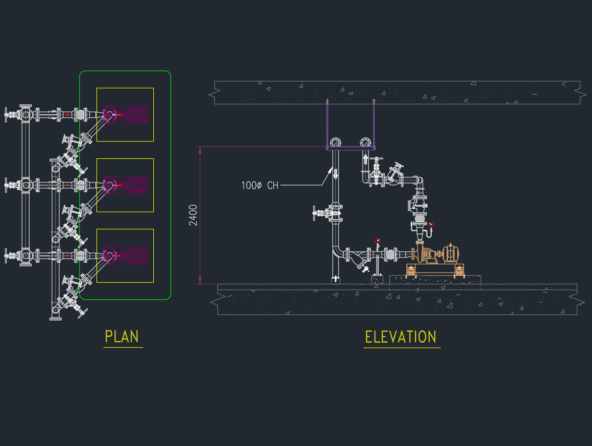
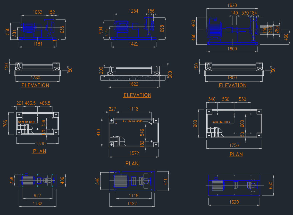
The Typical Chilled Water Pump Valve Assembly AutoCAD Drawing provides a complete layout showing the connection and valve arrangement around a chilled water pump in an HVAC system. This DWG file includes suction and discharge piping, isolation valves, check valves, flexible connectors, strainers, and pressure gauges — all organized for correct installation and maintenance access. Ideal for MEP engineers, HVAC designers, and contractors, this drawing ensures proper hydraulic balance and system reliability. Download this chilled water pump valve assembly AutoCAD DWG to improve your design documentation, enhance project coordination, and maintain professional engineering standards.

⬇ Download AutoCAD File
Share This:

More posts

  • Butterfly Valve DWG: Free AutoCAD Drawing for Industrial Use
  • Gate Valve DWG Download: AutoCAD Drawing for Industrial Use
  • Welding Tee AutoCAD Drawing for Pipe Fittings
  • Centrifugal Pump | AutoCAD Mechanical Drawing
  • Chilled Water Pump Valve Assembly AutoCAD Drawing
  • Bolt and Nuts | Drawing for Mechanical and Structural Design
  • Electrical Single Line Diagram of MTS in AutoCAD Drawing
  • Electrical Single Line Diagram for MSB With Panel Layout
  • Electrical Single Line Diagram of MDB | AutoCAD Drawing
  • Electrical Single Line Diagram of DB | AutoCAD Drawing
  • Electrical Single Line Diagram of ACP | AutoCAD Drawing
  • Single Line Diagram of MDB – AutoCAD Electrical CAD Drawing