Introduction
An Underground Ventilation Duct is an essential element of HVAC systems in large buildings, basements, or underground facilities. It allows air to circulate effectively through concealed pathways, maintaining proper ventilation and temperature control.
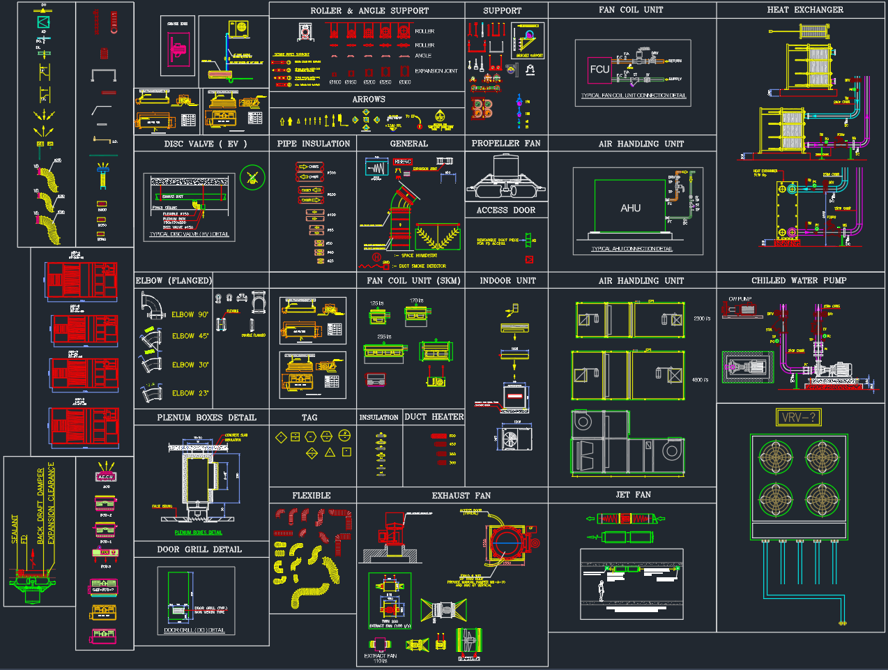
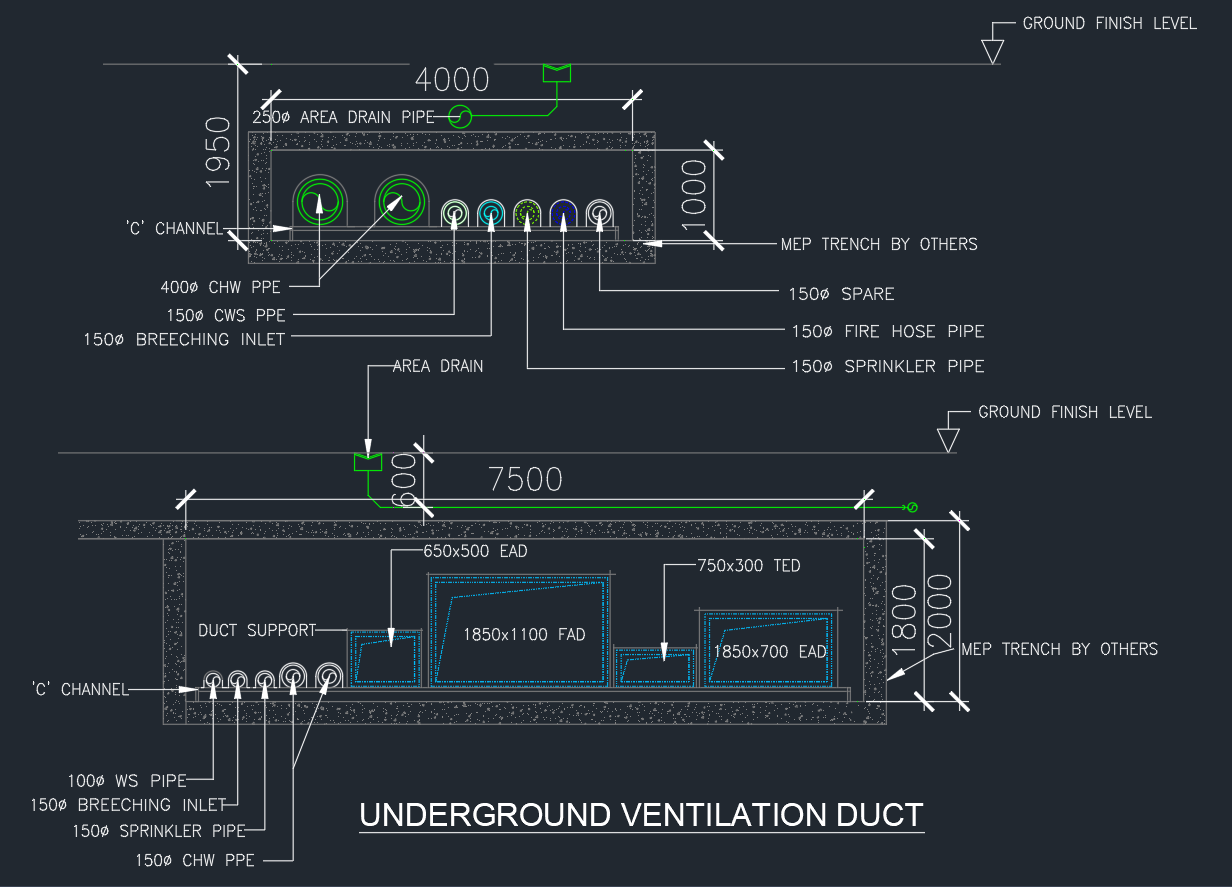
This AutoCAD DWG drawing illustrates a complete underground ventilation duct layout, including fresh air ducts (FAD), exhaust air ducts (EAD), treated exhaust ducts (TED), and associated MEP components such as fire pipes, chilled water lines, and drainage.
Components of the Underground Ventilation Duct
1. MEP Trench Construction
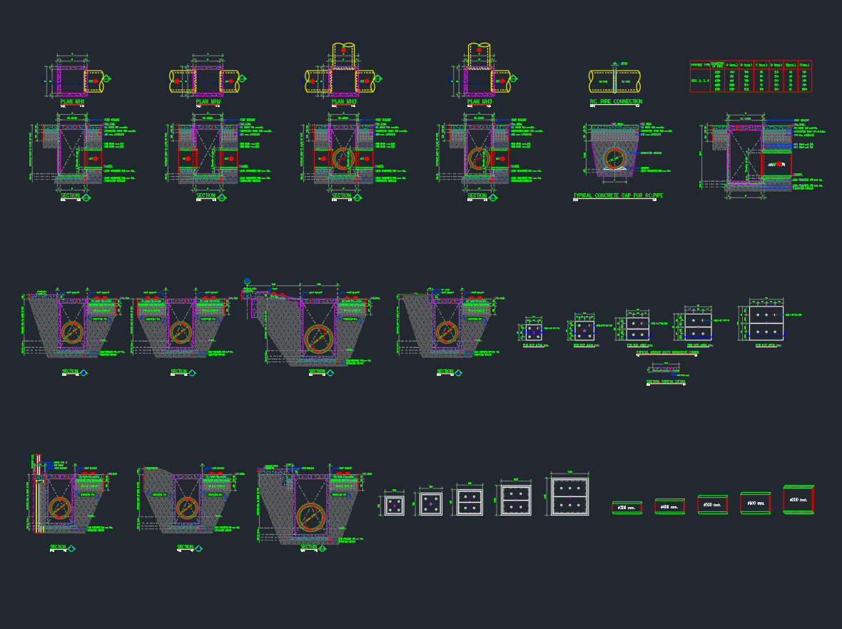
The trench acts as a protected corridor for multiple mechanical, electrical, and plumbing systems. It is made from reinforced concrete with waterproofing and proper access for inspection.
-
Typical width: 4000–7500 mm
-
Depth: 1000–2000 mm
-
Structure: Reinforced concrete with ‘C’ channel supports and area drains.
2. Ventilation Ducts
The layout includes three main duct types for efficient air handling:
-
FAD (Fresh Air Duct): 1850×1100 mm – delivers outdoor air into occupied spaces.
-
EAD (Exhaust Air Duct): 650×500 mm and 1850×700 mm – removes stale air.
-
TED (Treated Exhaust Duct): 750×300 mm – carries processed exhaust from air-handling units.
All ducts are shown mounted on duct supports with C-channel framing, ensuring alignment, load distribution, and vibration control.
3. Piping Systems in Trench
Multiple service lines are coordinated alongside the ducts:
-
400 mm Ø CHW Pipe: Chilled water supply for cooling systems.
-
150 mm Ø CWS Pipe: Chilled water return.
-
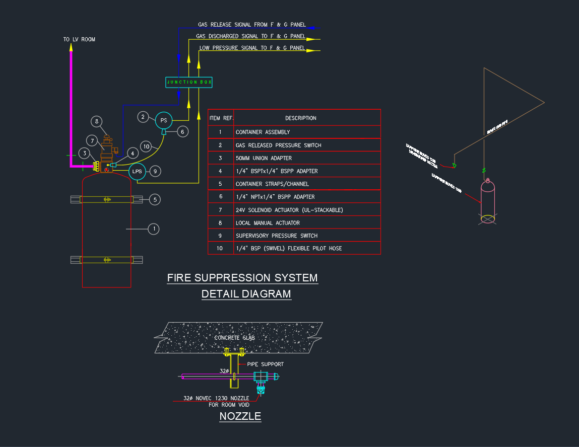
150 mm Ø Breeching Inlet: Fire service connection.
-
150 mm Ø Sprinkler Pipe: Fire protection distribution line.
-
100 mm Ø WS Pipe: Water supply line.
All pipes are positioned with proper spacing for accessibility and future maintenance.
4. Area Drain and Drain Pipe
A 250 mm Ø area drain pipe is installed to collect and discharge rainwater or condensation from the trench. The drain is connected to the main drainage system to prevent flooding and maintain dry conditions within the duct corridor.
5. ‘C’ Channel Supports
Steel ‘C’ channels are used to support ducts and pipes, providing stability, corrosion resistance, and easy installation. Galvanized or epoxy-coated channels are preferred for underground environments.
Functional Objectives
-
Efficient Airflow Distribution: Allows fresh and exhaust air movement through concealed ducts.
-
MEP Integration: Houses HVAC, plumbing, and fire systems in a single trench.
-
Space Optimization: Reduces ceiling congestion and maintains architectural aesthetics.
-
Service Accessibility: Provides safe and easy maintenance access.
-
Moisture and Fire Control: Incorporates drainage and fire-resistant design.
Design and Installation Considerations
1. Waterproofing and Insulation
-
Apply waterproof membranes along trench walls and base slab.
-
Insulate ducts and chilled water pipes to prevent condensation and heat loss.
2. Drainage and Ventilation
-
Ensure area drains are placed at the lowest points of the trench.
-
Install vent openings to balance air pressure and reduce moisture buildup.
3. Duct Material and Protection
-
Use galvanized or stainless-steel ducts with anti-corrosion coating.
-
Apply protective insulation wrap in high-humidity areas.
4. Thermal and Acoustic Performance
-
Use sound-dampening materials around ducts to minimize noise transmission.
-
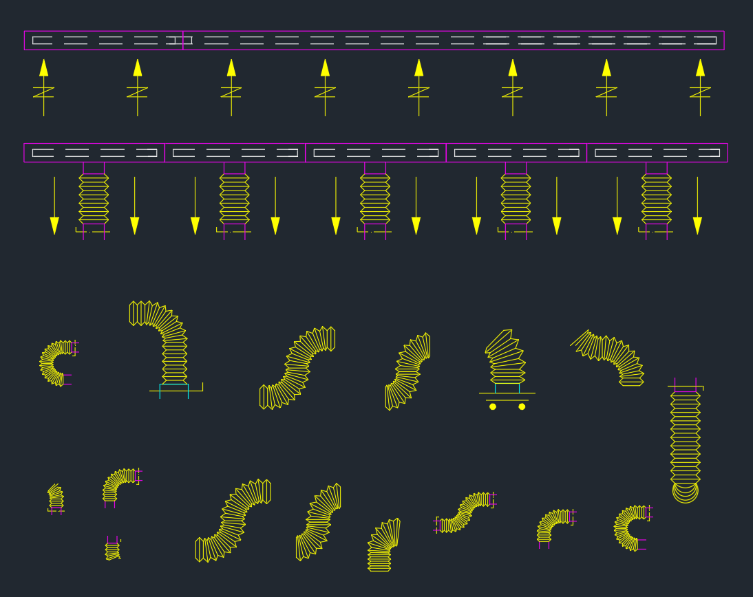
Include expansion joints to absorb thermal movement in long duct runs.
5. Safety and Compliance
-
Follow ASHRAE, NFPA, and SMACNA standards for HVAC duct and fire safety design.
-
Maintain clearance between HVAC ducts and electrical or fire lines.
Applications
The Underground Ventilation Duct is commonly used in:
-
Basement HVAC systems for commercial and residential towers.
-
Tunnels, subways, and metro stations for fresh air circulation.
-
Underground parking facilities for exhaust ventilation.
-
Industrial and plant buildings with underground utility corridors.
Including this DWG detail in project documentation ensures accurate construction, effective coordination, and compliance with mechanical design standards.
Conclusion
The Underground Ventilation Duct DWG drawing provides a clear and detailed representation of mechanical, plumbing, and ventilation systems within an underground trench. It helps MEP designers achieve precise coordination between air ducts, water pipes, and drainage elements.
By incorporating this detail, engineers can ensure efficient airflow, safe installation, and easy maintenance across HVAC and building service systems.
⬇ Download AutoCAD File