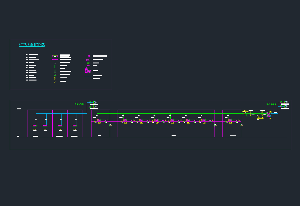
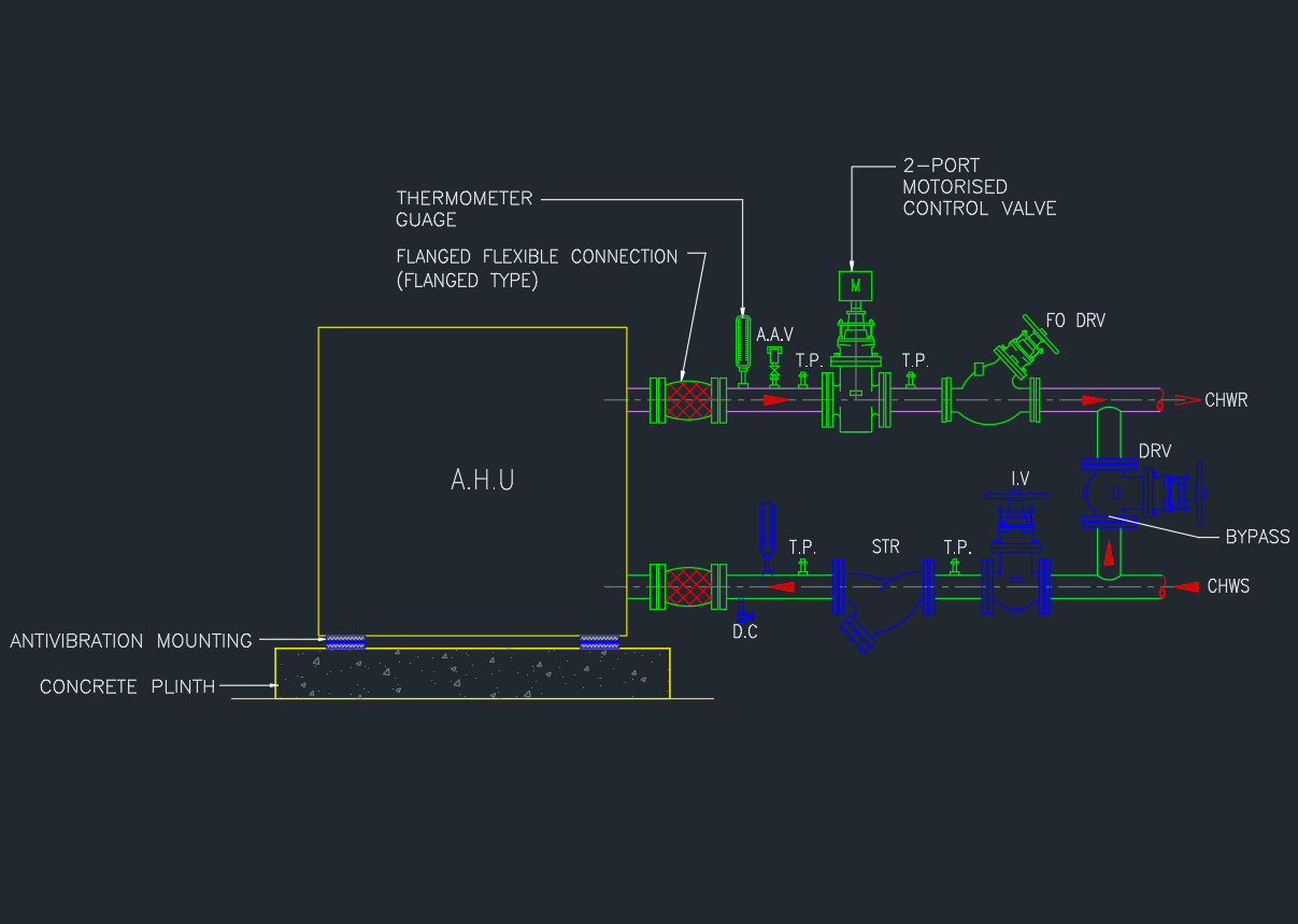
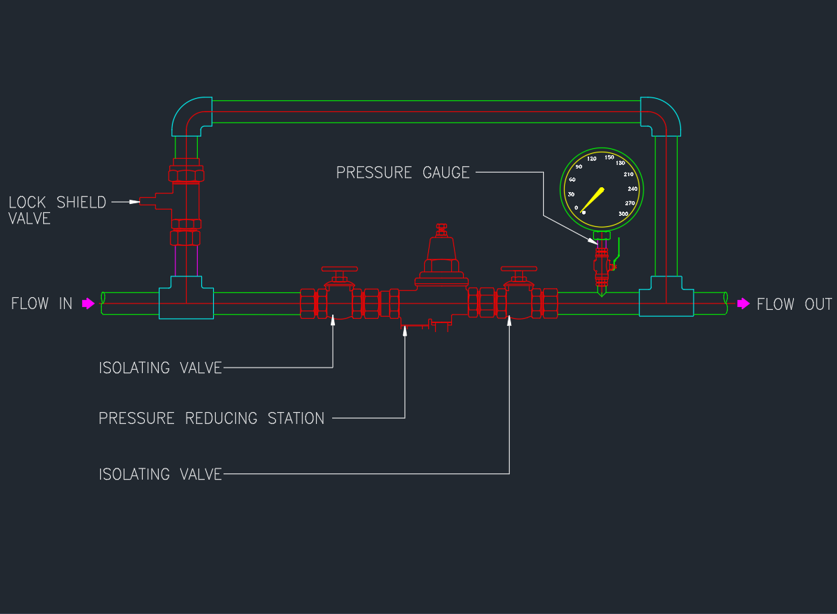
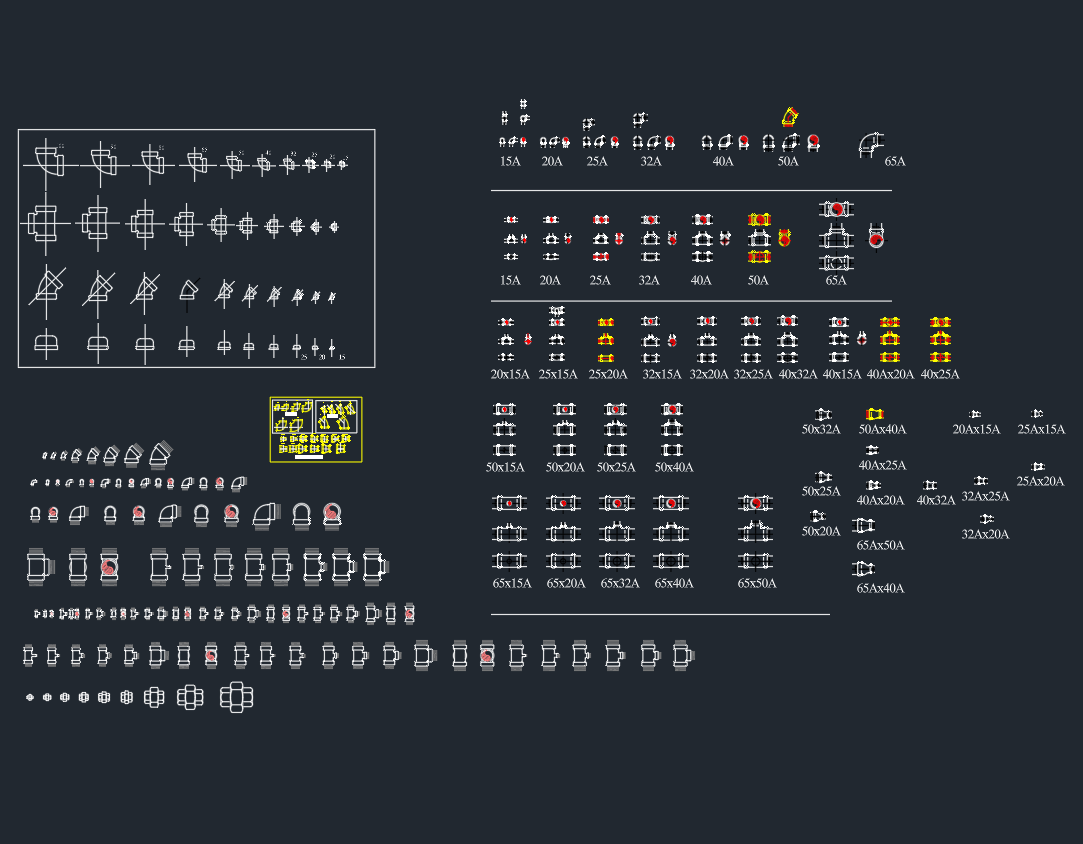
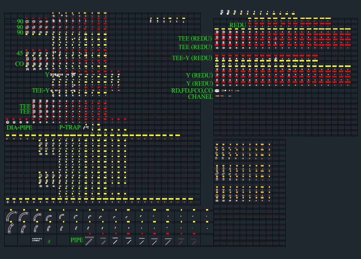
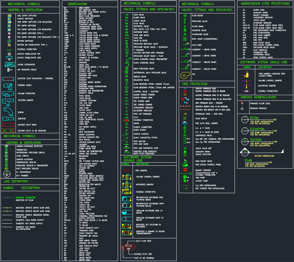
The Air System Schematic Diagram AutoCAD Drawing provides a complete layout of how air flows through supply, return, and exhaust systems in HVAC design. This DWG file includes air handling units (AHU), ducts, dampers, diffusers, and control components clearly represented in schematic form. It helps engineers and designers visualize airflow paths, system zoning, and pressure control for efficient building ventilation. Ideal for MEP engineers, HVAC designers, and contractors, this air system schematic AutoCAD DWG improves coordination, documentation, and performance in both commercial and industrial ventilation projects.
⬇ Download AutoCAD FileAir System Schematic Diagram | AutoCAD HVAC Drawing