Introduction
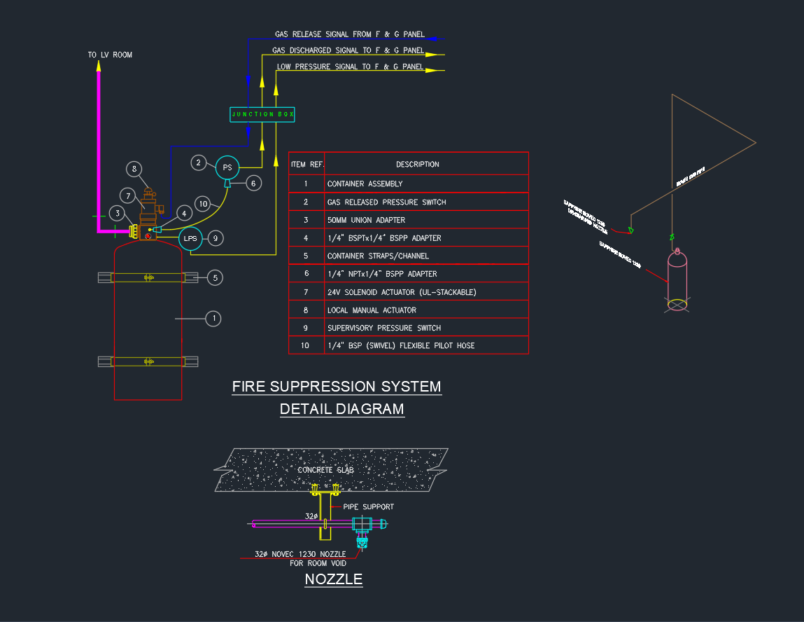
A Fire Suppression System is a critical component in building safety design, used to automatically detect and extinguish fires using gas-based or chemical suppression agents. This AutoCAD DWG detail drawing illustrates the components and wiring diagram of a gas-based fire suppression system, including a complete schematic for the Novec 1230 or FM-200 agent system.
This drawing is essential for MEP engineers, fire protection designers, and system installers working on commercial, data center, and control room safety systems.
Components in the Fire Suppression System Diagram
1. Container Assembly (Item 1)
The main cylinder stores the suppression agent—commonly Novec 1230 or FM-200—pressurized with nitrogen. It includes pressure gauges and mounting channels for secure installation.
2. Gas Released Pressure Switch (Item 2)
Detects pressure changes during system activation and sends a signal to the Fire Alarm & Gas (F&G) Panel for monitoring and alarm initiation.
3. Union Adapter (Item 3)
A 50 mm union adapter connects the gas container outlet to the discharge piping, ensuring a tight and secure joint for high-pressure flow.
4. Base and Pilot Line Connections (Items 4, 6, and 10)
-
BSP and NPT adapters connect actuator valves and pilot hoses.
-
The ¼” BSP flexible pilot hose transmits the pneumatic or electrical activation signal from the control valve to the main discharge valve.
5. Solenoid Actuator (Item 7)
The 24V DC solenoid actuator (UL-listed) is triggered by an electrical signal from the control panel. It opens the discharge valve to release the suppression agent through the piping network.
6. Manual Actuator (Item 8)
A local manual actuator allows on-site activation in case of panel failure or emergency manual override.
7. Supervisory Pressure Switch (Item 9)
Monitors system readiness by ensuring sufficient pressure inside the container. It alerts the control panel if pressure drops below the set threshold.
8. Nozzle and Discharge Assembly
Located under the ceiling or raised floor, the Novec 1230 nozzle ensures even distribution of the extinguishing agent within the protected area.
-
Designed for room void coverage.
-
Supported by pipe supports and secured under the concrete slab.
Signal and Control Flow
The system communicates with the Fire & Gas Control Panel (F&G Panel) through multiple signal types:
-
Gas Release Signal – From the panel to the solenoid actuator for system discharge.
-
Discharge Feedback Signal – Indicates successful gas discharge.
-
Low Pressure Signal – Triggers an alert when container pressure falls below operational limits.
-
Supervisory Signal – Sent continuously for pressure and readiness monitoring.
All signals are routed through a junction box and connected to the LV (Low Voltage) Room for integration with building management or fire alarm systems.
Key Notes and Standards
-
The suppression system complies with NFPA 2001 (Clean Agent Fire Extinguishing Systems) and UL 2166 for gaseous systems.
-
Piping material must withstand the design pressure (typically 25–42 bar).
-
The Novec 1230 agent is environmentally safe with zero ozone depletion potential (ODP) and low global warming potential (GWP).
-
Regular system maintenance and hydrostatic testing must be performed per manufacturer recommendations.
-
Ensure the nozzle discharge pattern provides full room coverage, considering room geometry and obstructions.
Applications
The Fire Suppression System shown in this DWG detail is commonly used in:
-
Server Rooms and Data Centers
-
Electrical Control Rooms and Substations
-
Telecommunication Facilities
-
Archives, Museums, and Laboratories
-
Commercial Buildings with Sensitive Equipment
The design ensures rapid fire detection and suppression with minimal collateral damage to electrical or electronic equipment.
Advantages of Gas-Based Fire Suppression
-
Fast Activation: Extinguishes fires within seconds.
-
Residue-Free: Leaves no water or foam residue, protecting sensitive equipment.
-
Environmentally Friendly: Uses clean agents like Novec 1230 or FM-200.
-
Safe for Occupied Areas: Non-toxic concentrations suitable for human occupancy.
-
Reliable Integration: Easily connects with alarm and building control systems.
Conclusion
The Fire Suppression System DWG Detail provides a complete and accurate representation of clean agent fire protection components, wiring, and nozzle installation. It is designed to help engineers and designers ensure safety compliance and effective protection in critical facilities.
By incorporating this DWG file into your MEP project, you can standardize documentation and streamline coordination between fire, electrical, and mechanical systems.
⬇ Download AutoCAD File