Introduction
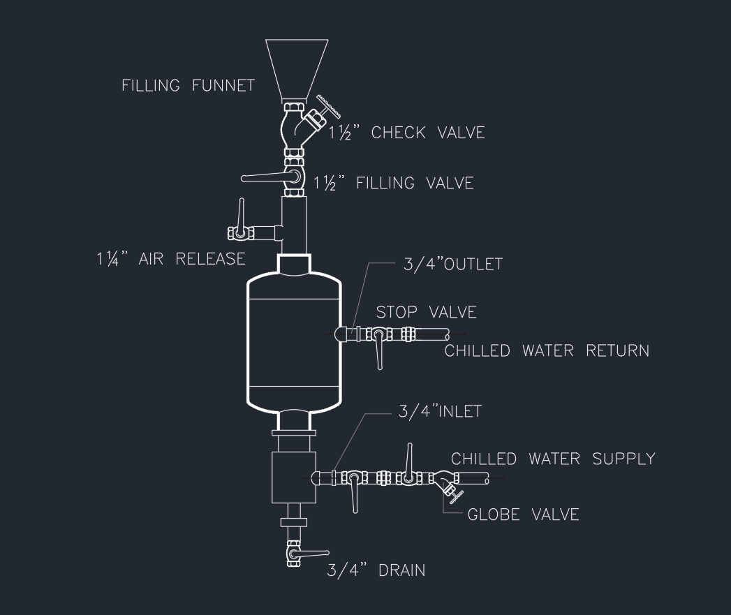
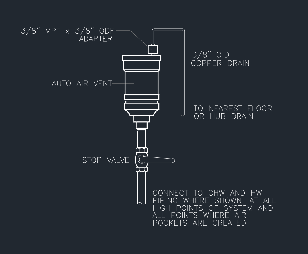
This Auto Air Vent AutoCAD DWG drawing provides a detailed installation diagram for an automatic air vent assembly used in CHW and HW systems.
It shows how the vent is connected at high points in piping systems to release trapped air — improving circulation and preventing air lock problems.
1. Drawing Information
| Feature | Description |
|---|---|
| File Format | DWG (AutoCAD 2007 and later) |
| View | Elevation / Schematic |
| Category | HVAC / Mechanical / Piping |
| System Type | Chilled Water & Hot Water |
| Compatibility | AutoCAD, BricsCAD, DraftSight, GstarCAD |
| Scale | 1:20 (schematic) |
🧩 Includes all key components labeled with pipe sizes and connection types.
2. Components Included
-
Auto Air Vent – Automatically discharges trapped air from system.
-
3/8″ MPT × 3/8″ ODF Adapter – Connects vent to copper piping.
-
3/8″ O.D. Copper Drain – Discharges air condensate to nearest hub or floor drain.
-
Stop Valve – Allows isolation during maintenance or replacement.
3. Installation Notes
-
Install at highest points of the system and any areas where air pockets form.
-
Drain line should be copper pipe (3/8″ O.D.), sloped to the nearest floor or hub drain.
-
Include isolation valve (stop valve) below vent for servicing.
-
For CHW and HW piping, locate near risers, coils, and air separators.
-
Seal threaded joints using PTFE tape or approved pipe sealant.
4. Applications
-
HVAC chilled water loops
-
Hot water circulation systems
-
Heating and cooling coils
-
Piping risers and air separators
-
Building hydronic systems
5. Download Auto Air Vent DWG Drawing
File Size: ~100 KB
License: Free for personal and educational use
6. Design Tips
✅ Always place auto air vents at system high points.
✅ Ensure drain piping slopes downward (min. 1%).
✅ Use brass or corrosion-resistant material for vent body.
✅ For maintenance, isolate vent with stop valve before removal.
✅ Do not install upside down or in vertical downward piping.
Conclusion
This Auto Air Vent DWG drawing provides a professional, ready-to-use CAD reference for HVAC and mechanical designers.
It clearly shows the vent assembly, connection adapter, copper drain, and isolation valve, ensuring reliable system air removal and easy maintenance.
⬇ Download AutoCAD File⚙️ Download this drawing now to enhance your HVAC CAD library with accurate piping and venting details.