CAD Blocks Hub for Industrial Design

Your Source for Engineering CAD Blocks & Typical Drawings

Pipe Support Through-Wall | AutoCAD Installation Detail

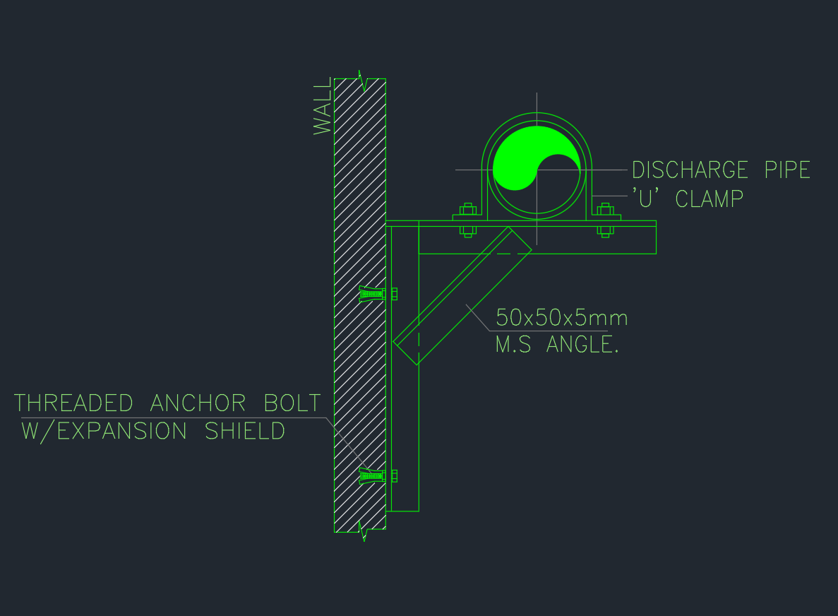
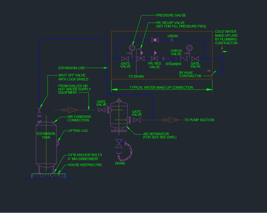
The Pipe Support Through-Wall Detail AutoCAD drawing provides a precise layout showing how mechanical and plumbing pipes are supported when passing through walls or partitions. This DWG file illustrates sleeve placement, anchor bolts, hangers, and structural supports to maintain alignment, minimize vibration, and ensure long-term stability. It is ideal for MEP engineers, piping designers, and contractors who need accurate installation guidance for HVAC, plumbing, or fire protection systems. Download this AutoCAD pipe support through-wall detail DWG to enhance your technical drawing library and ensure professional, code-compliant installation across all piping projects.

⬇ Download AutoCAD File
Share This:

More posts

  • Vibration Isolator AutoCAD Drawing for HVAC Equipment
  • Typical Heat Exchanger Connection Detail AutoCAD Drawing
  • Fresh Air Handling Unit Valve Arrangement AutoCAD Drawing
  • Expansion Tank and Air Separator Piping Diagram AutoCAD Drawing
  • Plate Heat Exchanger AutoCAD Drawing | Detailed Equipment
  • Heat Exchanger AutoCAD Drawing Professional Equipment Design
  • Flexible Joint in AutoCAD Drawing for Piping Systems
  • Check Valve AutoCAD Drawing | Detailed Equipment CAD Files
  • Stop Valve | AutoCAD Piping DWG Drawing
  • Y Type Strainer AutoCAD Drawing | Download Equipment CAD File
  • Double Seated Valve | AutoCAD Mechanical Drawing
  • Butterfly Valve DWG | Free AutoCAD Drawing for Industrial Use