CAD Blocks Hub for Industrial Design

Your Source for Engineering CAD Blocks & Typical Drawings

Zonal Control Valve CAD Block | AutoCAD Drawing Details

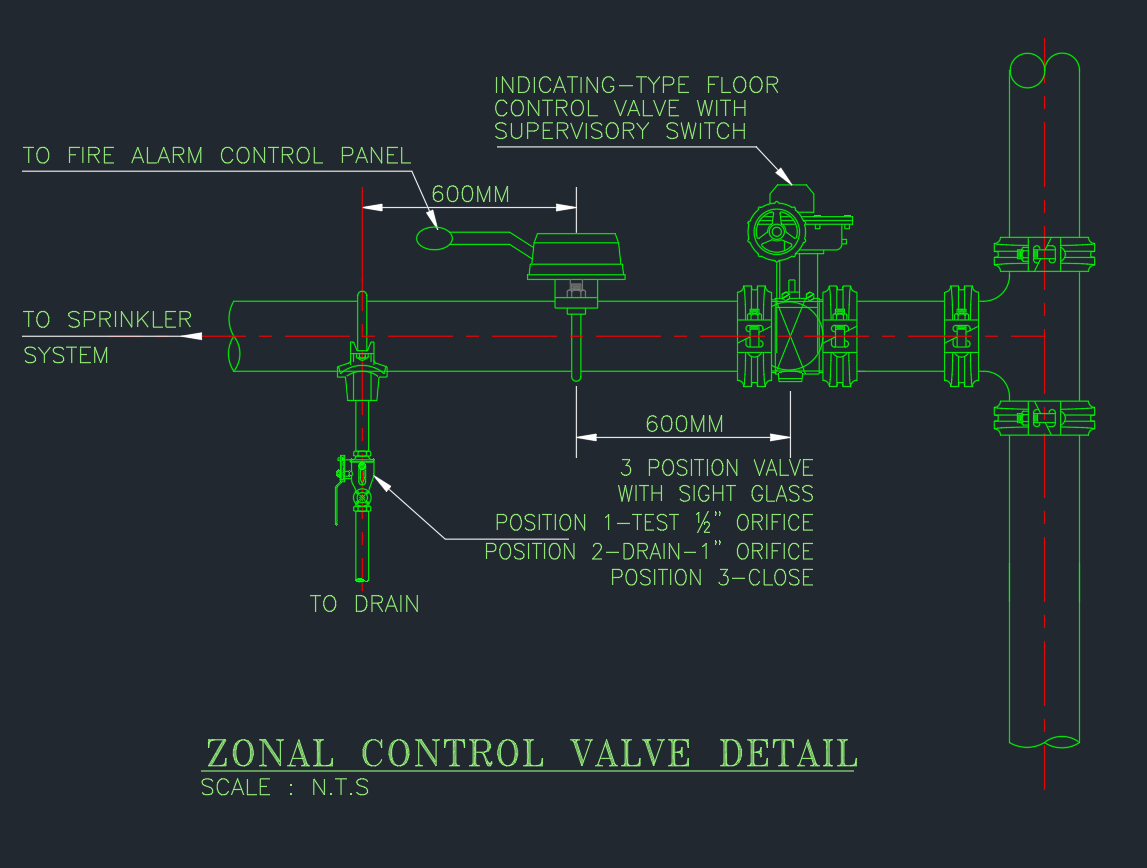
The Zonal Control Valve Detail AutoCAD drawing provides a clear layout of the essential components used in fire sprinkler systems to isolate and control water flow within specific zones. This DWG file includes the valve assembly, flow switch, pressure gauge, test drain, and alarm connection — all shown with professional detailing. Ideal for fire protection engineers, MEP designers, and contractors, this drawing ensures proper system segmentation, maintenance access, and compliance with NFPA standards. Download this zonal control valve detail DWG to enhance your AutoCAD library and improve the accuracy of your fire system design documentation.

⬇ Download AutoCAD File
Share This:

More posts

  • Vibration Isolator AutoCAD Drawing for HVAC Equipment
  • Typical Heat Exchanger Connection Detail AutoCAD Drawing
  • Fresh Air Handling Unit Valve Arrangement AutoCAD Drawing
  • Expansion Tank and Air Separator Piping Diagram AutoCAD Drawing
  • Plate Heat Exchanger AutoCAD Drawing | Detailed Equipment
  • Heat Exchanger AutoCAD Drawing Professional Equipment Design
  • Flexible Joint in AutoCAD Drawing for Piping Systems
  • Check Valve AutoCAD Drawing | Detailed Equipment CAD Files
  • Stop Valve | AutoCAD Piping DWG Drawing
  • Y Type Strainer AutoCAD Drawing | Download Equipment CAD File
  • Double Seated Valve | AutoCAD Mechanical Drawing
  • Butterfly Valve DWG | Free AutoCAD Drawing for Industrial Use