CAD Blocks Hub for Industrial Design

Your Source for Engineering CAD Blocks & Typical Drawings

Single Line Diagram of Power System Explained

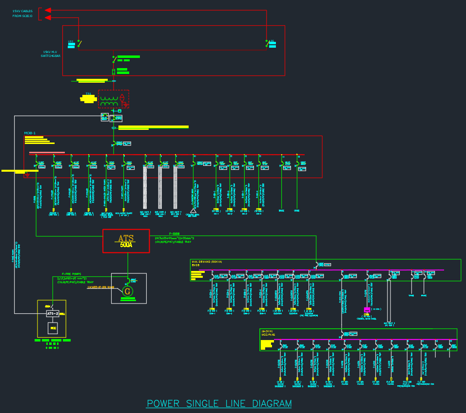
A Single Line Diagram (SLD) is one of the most essential drawings in electrical power engineering. It represents how electrical power flows from the generating source to the load through transmission lines, transformers, circuit breakers, and other equipment using simple symbols and a single line. This diagram helps engineers, designers, and electricians understand the system configuration, fault levels, and protection coordination in large electrical networks. In this guide, you’ll learn the key components, symbols, and layout of a power system single line diagram — an important tool for safe design, operation, and maintenance in any industrial or commercial facility.

⬇ Download AutoCAD File
Share This:

More posts

  • Vibration Isolator AutoCAD Drawing for HVAC Equipment
  • Typical Heat Exchanger Connection Detail AutoCAD Drawing
  • Fresh Air Handling Unit Valve Arrangement AutoCAD Drawing
  • Expansion Tank and Air Separator Piping Diagram AutoCAD Drawing
  • Plate Heat Exchanger AutoCAD Drawing | Detailed Equipment
  • Heat Exchanger AutoCAD Drawing Professional Equipment Design
  • Flexible Joint in AutoCAD Drawing for Piping Systems
  • Check Valve AutoCAD Drawing | Detailed Equipment CAD Files
  • Stop Valve | AutoCAD Piping DWG Drawing
  • Y Type Strainer AutoCAD Drawing | Download Equipment CAD File
  • Double Seated Valve | AutoCAD Mechanical Drawing
  • Butterfly Valve DWG | Free AutoCAD Drawing for Industrial Use